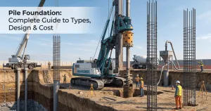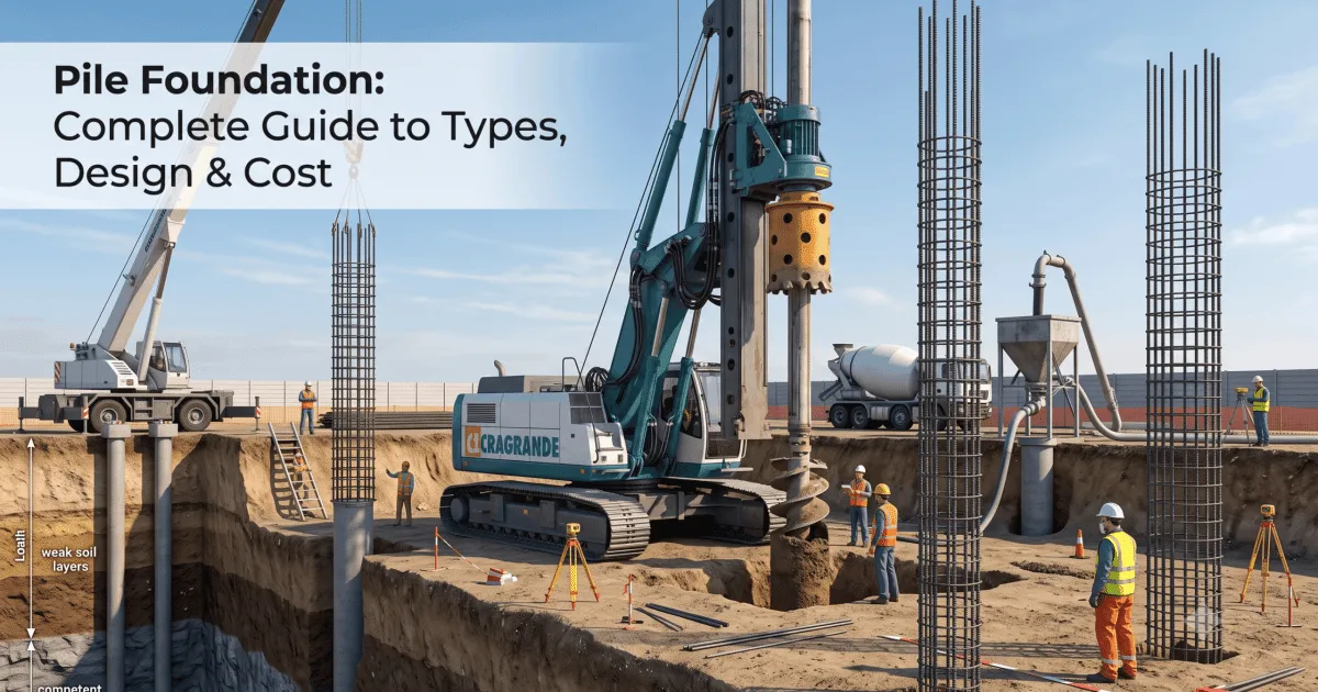
If you’ve ever watched a construction crew drive a rig into the ground for hours before a single column goes up, you’ve watched pile foundation work happen. It’s one of those parts of a project that nobody photographs for the brochure, but without it, the tower, the bridge, or the tank farm next to it simply wouldn’t stand.
A pile foundation is a deep foundation system that carries a structure’s load down through weak or unstable soil layers until it reaches ground that can actually support the weight. That could be a hard bearing stratum or, in the case of friction piles, enough soil resistance along the pile’s length to hold everything up without excessive settlement. Think of it as a set of long, slender columns buried in the earth, each one doing the job a shallow footing can’t do when the soil near the surface is too soft, too loose, or too unpredictable.
Engineers reach for piles in a specific set of situations: soft clay or loose sand near the surface, high water tables, heavy structural loads concentrated on small footprints (think high-rises), bridges crossing rivers, and marine structures sitting in water for their entire service life. In Muscat and across the Gulf, you’ll see piling rigs on almost every large commercial site. Much of the coastal soil profile here simply can’t carry heavy loads on a spread footing without piles doing the real work underneath.
The difference between shallow and deep foundations comes down to depth relative to width. A shallow foundation (a pad footing, a strip footing, a raft) sits close to the surface and spreads load over a wide area. A deep foundation, piles included, transfers load much further down, often tens of meters, to reach soil or rock that’s actually competent. The choice between the two isn’t a style preference. It’s driven by geotechnical data, structural loads, and, frankly, by what the soil investigation report tells you about what’s underneath the site.
This guide walks through the full picture: what pile foundations are, how they work, every major type you’ll come across on a real job (driven, bored, precast, helical, screw, micropiles, and more), how pile caps and reinforcement details come together, how deep piles typically need to go, how they’re tested once installed, and where the relevant IS and BS/Eurocode standards fit into the picture. Wherever it’s useful, I’ve added comparison tables and construction sequence breakdowns you can actually use on site, not just read about.
What is a Pile Foundation?
A pile foundation is a slender structural element, made of concrete, steel, or timber, driven or bored deep into the ground to transfer building loads from weak surface soil down to a stronger bearing layer or to soil that offers enough frictional resistance to support the structure safely. It’s used when shallow foundations can’t provide adequate bearing capacity or when settlement needs to stay within tight limits.
The working principle is straightforward once you strip away the jargon. A column brings load down onto a pile cap. The pile cap spreads that load across a group of piles. Each pile then pushes that load further down, either onto a hard layer (end bearing) or out sideways into the surrounding soil through friction along its shaft (skin friction), or usually some mix of both.
Why do engineers choose piles over a simple footing? Because a footing only works if the soil directly beneath it is strong enough to take the pressure without excessive settlement or shear failure. When that soil is soft clay, loose fill, reclaimed land, or sits above a high water table, a spread footing either needs to be enormous, which gets expensive and impractical fast, or it needs help. Piles are that help. They bypass the weak zone entirely and reach something better.
Quick definition (for search snippets): A pile foundation is a deep foundation type using long structural members, called piles, driven or bored into the ground to transfer structural loads through weak soil to a stronger stratum below, providing support through end bearing, skin friction, or both.
Pile Foundation Diagram
Image Suggestion: An educational cross-section diagram showing a column sitting on a reinforced pile cap, with two or more piles extending down through a layer of weak soil into a hard bearing stratum. Alt text: “Pile foundation diagram showing pile cap, column, reinforcement, weak soil layer, and hard bearing strata.”
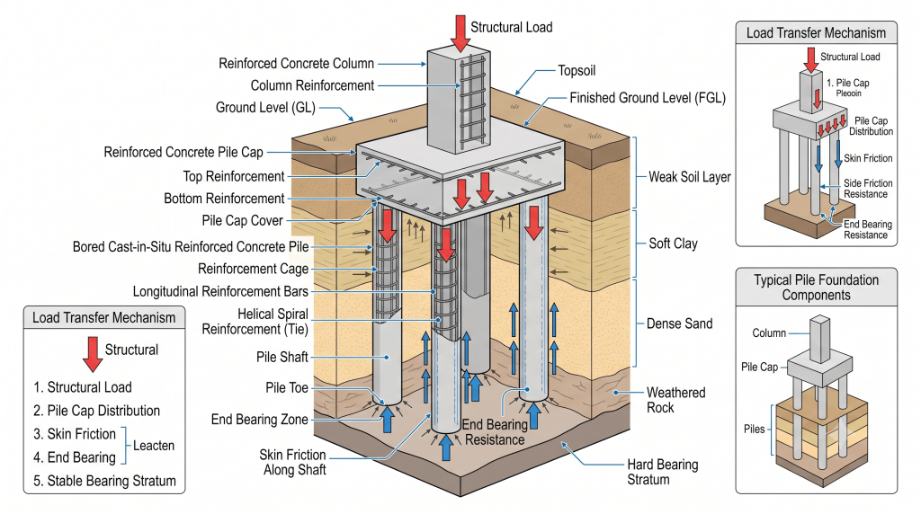
Here’s what each labeled part of that cross-section actually does:
- Column: brings the structural load down from the superstructure.
- Pile cap: a thick reinforced concrete slab sitting on top of the piles, tying the pile group together and distributing the column load evenly across every pile beneath it.
- Reinforcement: steel bars running the length of the pile (longitudinal) plus spiral or ring ties (transverse), giving the pile the strength to resist bending, handling stresses during driving, and, in seismic zones, lateral loads.
- Pile shaft: the main body of the pile, running from just below the cap down to the toe.
- Ground level: the natural surface elevation before excavation.
- Weak soil: the loose, soft, or compressible layer near the surface that can’t carry the load on its own; this is exactly what the pile is bypassing.
- Hard strata: the competent layer at depth (dense sand, gravel, or rock) that the pile toe rests on for end-bearing action, or that surrounding soil the pile relies on for friction.
If you’re new to reading these drawings, the one thing to remember is this: everything above the weak soil line is “structure,” and everything the pile passes through below it is “problem the pile is solving.”
How Does a Pile Foundation Work?
A pile carries load in one of two fundamental ways, and almost every real pile does a bit of both.
End bearing action happens at the toe of the pile. The pile behaves like a very long column, transferring load down to a hard stratum (dense sand, gravel, or rock) that can take the pressure without significant compression. Picture pushing a stick down through soft mud until the tip hits a concrete slab underneath. The stick barely compresses; the slab takes the load. That’s end bearing.
Skin friction works differently. As load pushes the pile downward, the soil in contact with the pile’s surface resists that movement through friction and adhesion along the entire embedded length. A long pile in stiff clay might never touch a hard layer at all. It doesn’t need to, because the accumulated friction along, say, 20 meters of shaft is enough to hold the load. Picture a nail in wood: it’s not resting on anything at its tip, but friction along its length keeps it from pulling out.
Most piles use a combined action of both mechanisms, though one usually dominates depending on the soil profile. A pile driven through loose sand into dense gravel will lean heavily on end bearing. A pile embedded entirely in stiff clay with no rock in reach will lean on friction.
The soil interaction matters just as much during construction as during service life. Driving a pile densifies loose granular soil around it (which is actually a benefit, since it’s why displacement piles work so well in sand), while boring a pile in clay can disturb and soften the soil right at the shaft interface if drilling fluid or slurry isn’t managed properly. That disturbance is exactly why bored pile skin friction values in design codes are often lower than for driven piles in the same soil.
Settlement control is the other half of the story. A well-designed pile group doesn’t just avoid outright failure. It keeps total and differential settlement within limits the structure can tolerate, typically 25mm total and much less differential for most buildings. Even a friction pile with plenty of capacity can settle more than expected if the pile spacing is too tight and overlapping stress zones between adjacent piles add up in the soil below.
Why Use Pile Foundations?
Piles show up whenever the ground, the load, or the structure’s tolerance for movement makes a shallow foundation impractical.
Soft soil. Reclaimed coastal land, soft marine clay, and loose fill are the classic triggers. A spread footing on this kind of ground would either sink unevenly or need to be so large it stops making economic sense.
High-rise buildings. Tall structures concentrate enormous loads onto relatively small footprints. Even decent soil can’t always take that pressure without piles spreading the load to depth.
Bridge foundations. Piers sitting in a riverbed or over variable alluvial deposits need piles to reach stable ground below the scour zone, which we’ll get to later.
Marine structures. Jetties, quays, and offshore platforms sit permanently in or near water, where the upper soil is often loose, saturated, and subject to wave and current action.
Industrial buildings. Heavy machinery foundations and process structures often carry large point loads and vibration, both of which favor a deep foundation system.
Water tanks. Elevated tanks, especially when full, put huge concentrated loads on a relatively compact base. Piles keep settlement uniform so the tank doesn’t tilt.
Transmission towers. These structures deal with significant uplift and lateral wind load, not just vertical weight, and piles (particularly under-reamed or anchor piles) resist that uplift well.
Retaining structures. Sheet piles and soldier pile walls hold back soil laterally, often as both a temporary excavation support and a permanent retaining system.
Types of Pile Foundation
Piles get classified a few different ways, and it helps to know all of them because job specs and IS/BS references mix terminology constantly. Below are the four classification systems you’ll actually use.
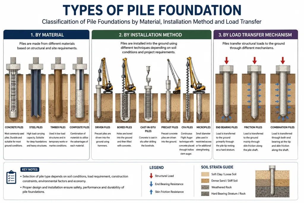
Based on Material
Concrete piles: the most common choice worldwide, available as precast or cast-in-situ. Durable, strong in compression, and adaptable to almost any soil condition. The tradeoff is weight (precast piles are heavy to transport and handle) and the risk of concrete quality issues in cast-in-situ work if the pour isn’t controlled properly.
Steel piles: H-piles or tubular (pipe) piles, valued for high strength-to-weight ratio and ease of splicing when extra length is needed mid-drive. They handle hard driving into dense soil or through obstructions better than concrete, but corrosion is the constant concern, especially in marine or aggressive soil environments, unless coatings or cathodic protection are specified.
Timber piles: largely a legacy option in most regions now, but still used in some temporary works and in specific soft-ground marine applications where they stay permanently submerged (timber below the permanent water table resists decay well; timber that cycles wet-dry rots fast). Cheap and easy to handle, but limited in length and load capacity compared to concrete or steel.
Composite piles: combine two materials along their length, commonly a concrete upper section with a timber or steel lower section, to get durability where it matters (near the surface, exposed to oxygen and moisture cycling) and economy where it doesn’t (fully submerged sections).
| Material | Typical Load Capacity | Durability | Cost | Best Suited For |
|---|---|---|---|---|
| Concrete (precast) | High | Very good | Moderate-High | General building work, marine structures with protective cover |
| Concrete (cast-in-situ) | High | Good (depends on QC) | Moderate | Sites needing variable pile lengths, urban infill |
| Steel | Very high | Moderate (corrosion risk) | High | Hard driving, obstructions, heavy industrial loads |
| Timber | Low-Moderate | Good if fully submerged | Low | Temporary works, light structures, historic/marine applications |
| Composite | Moderate-High | Good | Moderate | Marine piles with a dry/wet transition zone |
Based on Installation
Driven piles – precast concrete, steel, or timber piles hammered, vibrated, or pushed into the ground. Installation displaces soil outward, often improving the density of loose granular soil around the pile. Fast to install once mobilized, but driving generates noise and vibration that can be a real problem near existing structures or in dense urban sites.
Bored piles – formed by drilling a hole first (with or without temporary casing or drilling fluid to keep the hole stable) and then placing a reinforcement cage and pouring concrete in place. Quieter than driving, and better suited to sites with buildings close by, but quality depends heavily on how well the hole is cleaned and how the concrete pour is controlled.
Cast-in-situ piles – a broader category that includes bored piles but also covers driven-cast piles, where a steel shell or casing is driven into the ground and then filled with concrete, sometimes with the casing left in place and sometimes withdrawn as the concrete is placed.
Precast piles – manufactured off-site under controlled conditions, then transported and driven or jacked into position. Quality control is easier since casting happens in a yard, not in the ground, but you’re limited by transport length and by the pile’s ability to survive handling and driving stresses.
Continuous Flight Auger (CFA) piles – a specialized bored pile method where concrete is pumped through the hollow stem of the auger as it’s withdrawn, filling the hole from the bottom up in one continuous operation. This largely eliminates the risk of soil collapse into an open hole and works well in a wide range of soils, including below the water table.
Micropiles – small-diameter (typically under 300mm) piles, often drilled and grouted, used where access is tight or where existing foundations need underpinning. More on these later in the dedicated section.
Based on Load Transfer
End bearing piles rely almost entirely on the resistance of a hard stratum at the pile toe. Friction piles rely on skin friction along the shaft in soil with no accessible hard layer. Combination piles use both mechanisms simultaneously, which, honestly, describes the majority of real-world piles once you run the numbers – pure end bearing or pure friction piles are more of a textbook simplification than a field reality.
| Type | Primary Load Path | Typical Soil Condition | Example Use |
|---|---|---|---|
| End bearing | Pile toe to hard stratum | Hard rock or dense gravel at reachable depth | High-rise columns over rock at moderate depth |
| Friction | Skin resistance along shaft | Deep stiff clay, no accessible hard layer | Bridge piers in thick alluvial deposits |
| Combination | Both toe and shaft resistance | Mixed soil profile | Most real-world building and bridge piles |
Based on Function
Compaction piles – driven purely to densify loose granular soil, not necessarily to carry load themselves (sometimes they’re not even structural piles at all, just displacement elements).
Anchor piles – resist uplift or overturning forces, common under transmission towers and structures exposed to significant wind or seismic uplift.
Sheet piles – interlocking sections (steel, vinyl, or concrete) driven side by side to form a continuous wall, used for retaining soil or water, cofferdams, and riverbank protection.
Fender piles – installed at jetties and berths to absorb the impact energy of docking vessels, protecting both the ship and the structure.
Tension piles – designed specifically to resist uplift forces, similar in purpose to anchor piles but often used more generally for any structure where net upward force exceeds dead load, like a basement slab under hydrostatic pressure.
Settlement-reducing piles – used alongside a raft foundation not to carry the full building load themselves, but to reduce overall and differential settlement of the raft. This is the basis of the modern “piled raft” foundation concept, which blends the two systems rather than treating them as either/or.
Bored Pile Foundation
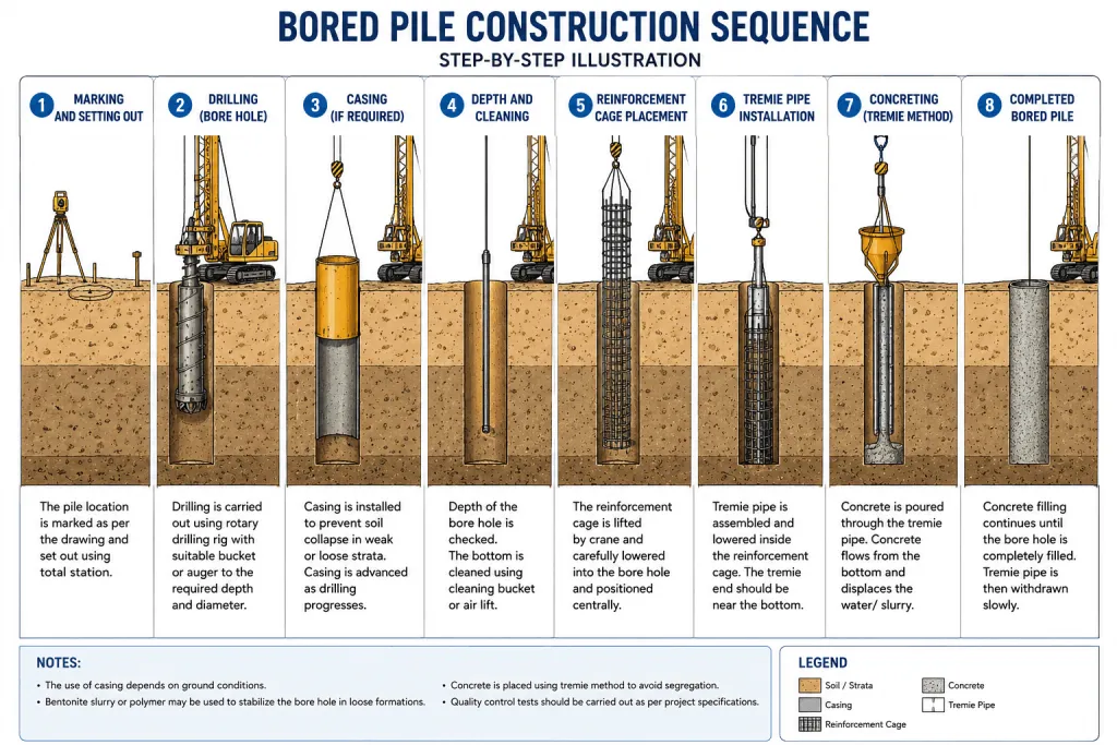
A bored pile foundation is formed by drilling (or “boring”) a cylindrical hole into the ground, placing a steel reinforcement cage inside it, and then filling the hole with concrete. It’s the go-to method whenever site conditions rule out driving, whether that’s noise restrictions, nearby structures sensitive to vibration, or a soil profile with obstructions a hammer just can’t push through.
Construction sequence:
- Set up the rig over the marked pile position and drill using a rotary auger or bucket, advancing through the soil.
- Insert a temporary casing near the top of the bore if the upper soil is loose or caving, or use bentonite/polymer drilling fluid to stabilize the hole walls as drilling continues.
- Drill to the design depth, confirmed against the geotechnical profile (and sometimes verified on-site by the engineer inspecting cuttings).
- Clean the base of the hole thoroughly. This step gets skipped or rushed more often than it should, and a dirty base is one of the most common causes of poor pile performance.
- Lower the pre-fabricated reinforcement cage into the hole, supported so it doesn’t sit on the base.
- Place concrete using a tremie pipe, working from the bottom up, so the concrete displaces drilling fluid or water rather than mixing with it.
- Withdraw the casing (if used) as concreting proceeds, keeping enough concrete head inside the casing to prevent soil or water intrusion.
- Trim the pile head to design cut-off level once the concrete has cured enough to handle it.
Advantages: minimal vibration and noise, adaptable to very large diameters and depths, works in mixed and obstructed ground, and length can be adjusted on the spot based on what the drilling actually reveals rather than being fixed in advance like a precast pile.
Disadvantages: quality is harder to verify than with driven piles (you can’t “see” the finished product the way you can inspect a precast unit), concreting under drilling fluid demands strict technique, and production rates are generally slower than driven piling.
Applications: urban sites with nearby existing structures, high-rise buildings needing large-diameter, high-capacity piles, and bridge piers where large single piles replace a cluster of smaller ones.
Common diameters range from about 600mm for smaller structures up to 1500mm or more for heavily loaded columns and bridge piers, with 900mm and 1200mm being frequent choices on mid-to-large commercial buildings.
Common depths vary hugely with the geology, but 15 to 40 meters is a typical working range for building foundations, and much deeper (60m+) isn’t unusual for major bridge or marine works where the bearing stratum sits well below the surface.
Machinery used includes rotary drilling rigs, rotary bucket rigs, hydraulic rotary piling rigs, and, for smaller diameter or restricted-access work, CFA rigs.
Quality control on a bored pile job comes down to a handful of checks done consistently: verifying founding depth against the geotechnical report, checking base cleanliness before concreting, monitoring concrete volume placed against theoretical volume (a shortfall often signals a void or soil intrusion), and running post-construction integrity tests.
Helical Pile Foundation
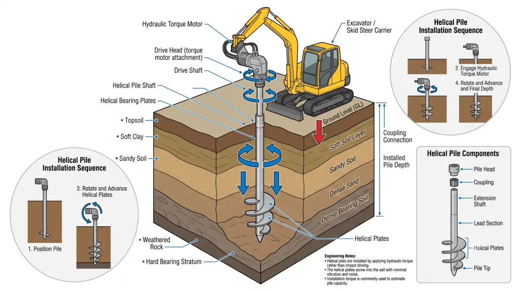
A helical pile foundation uses a steel shaft fitted with one or more helix-shaped plates, screwed into the ground much like a large screw driving into wood. There’s no excavation and no concrete curing time involved. The pile is simply torqued into the soil until it reaches the specified depth or, more precisely, the specified installation torque.
Definition and construction: helical piles consist of a central steel shaft (round or square) with helical bearing plates welded at intervals along the lower section. They’re manufactured off-site to exact specifications and installed as a complete unit, sometimes with extension sections added as the pile advances.
Installation: a hydraulic drive head, mounted on an excavator or dedicated rig, rotates the pile into the ground. The helix plates cut into the soil and pull the shaft downward with each rotation, similar to a wood screw.
Torque method: installation torque correlates directly with the soil’s resistance, and therefore with the pile’s ultimate capacity. Most helical pile design uses an empirically derived torque-to-capacity correlation, so the installer monitors torque in real time and stops (or knows the pile has reached adequate capacity) once the target value is hit consistently over the last meter or so of installation. It’s one of the few pile types where you get instant, on-site confirmation of load capacity rather than waiting for a separate load test.
Advantages: fast installation with no curing time (the structure can often be loaded almost immediately), minimal soil disturbance and spoil, works well in restricted-access sites, easily removable if needed, and the real-time torque feedback gives good confidence in capacity without always needing a separate load test.
Limitations: capacity per pile is generally lower than large-diameter driven or bored piles, so more piles are often needed for heavy loads. Performance in soil with cobbles, boulders, or very dense layers can be inconsistent since the helix can’t always advance cleanly through obstructions, and long-term corrosion protection matters as much as it does for any steel pile.
Residential applications: foundation underpinning, deck and porch footings, additions to existing structures where access for large rigs is limited, and light structure foundations on problem soils like expansive clay.
Commercial applications: solar farm racking foundations, telecommunications tower foundations, boardwalks, light industrial buildings, and temporary or relocatable structure foundations.
Screw Pile Foundation
A screw pile foundation works on essentially the same physical principle as a helical pile (a threaded or helix-bearing shaft rotated into the ground), but the term is often used more broadly to describe a family of screw-in foundation elements, ranging from small residential screw piers to larger helical piles used in commercial and marine work. In everyday site language, “screw pile” and “helical pile” get used almost interchangeably, though some manufacturers and regional standards draw a finer distinction based on shaft geometry and plate configuration.
Working: rotation drives the helical plate(s) into the soil, generating downward thrust with each turn, similar to how a wood screw advances through timber without needing a pre-drilled hole.
Installation: typically done with a hydraulic rotary head mounted on a mini excavator, skid steer, or dedicated piling rig, capable of applying both rotational torque and downward pressure.
Difference from helical piles: in strict engineering usage, a “helical pile” often refers to a shaft with distinct, separated helix plates designed primarily for axial load transfer, while “screw pile” sometimes describes a continuous helix or threaded shaft used more for smaller-scale or marine applications (screw piles have a long history in coastal lighthouse and jetty construction, predating modern helical pile design by well over a century). In practice, treat the terms as regionally interchangeable unless a specific manufacturer’s product literature or a project specification draws a line between them.
Advantages: rapid installation, no spoil removal, immediate load capacity confirmation via torque, good performance in soft or waterlogged ground where other equipment struggles to get access, and easy removal for temporary works.
Applications: boardwalks and jetties, coastal and marine structures, solar and telecom infrastructure, light-to-medium residential and commercial foundations, and temporary works where the foundation needs to be removable at the end of a project.
Pile Cap
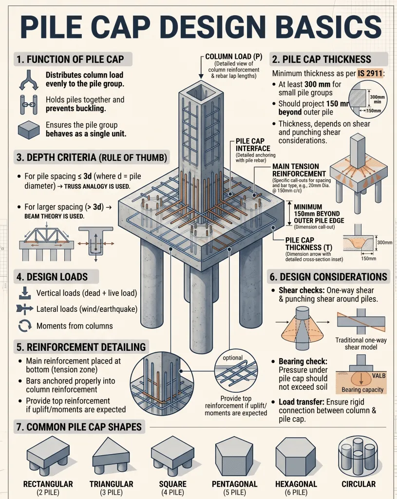
Definition: a pile cap is a thick reinforced concrete slab that sits directly on top of a pile or group of piles, tying them together structurally and transferring the column or wall load down into the piles as evenly as possible.
Functions: distribute the superstructure load across all piles in the group, tie the piles together so they act as a single unit rather than independent elements, resist bending and shear from the column load spreading out to each pile, and provide a level, uniform surface to build the column or wall on regardless of small variations in individual pile position or cut-off level.
Types:
- Single pile cap: used under a single pile carrying a light column load, essentially just a connector between column and pile.
- Two-pile cap: typically rectangular, designed to resist bending like a simple beam spanning between the two piles.
- Three-pile and four-pile caps: triangular or square in plan, common under moderately loaded columns.
- Multi-pile caps: used under heavily loaded columns or shear walls, sometimes irregular in shape to suit pile layout constraints.
- Combined pile caps: span across two or more columns, often used when columns are close together or when one column falls near a property boundary and its piles need to be shared with the adjacent column’s cap.
Design considerations: pile caps are typically designed using either simple beam theory (for smaller caps) or strut-and-tie modeling (for deep caps with a low span-to-depth ratio, which is the more accurate approach recognized in most modern codes for this kind of deep, non-flexural member). Punching shear around the column and around individual piles is almost always the governing check, not bending.
Reinforcement details: bottom reinforcement runs in both directions, concentrated in bands over the piles where strut-and-tie design is used, since that’s where the tension ties actually sit. Top reinforcement is added when there’s a risk of cap uplift or when the cap spans between widely spaced piles. Reinforcement needs to extend far enough into the cap to develop full bond strength (development length) beyond the critical section, and pile heads typically need to be embedded a nominal distance into the cap, with reinforcement or dowels from the pile projecting into the cap to ensure proper load transfer.
Minimum thickness: governed by punching shear and by the need for adequate anchorage of pile and column reinforcement. Thin caps are rarely economical anyway since punching shear demands usually push the required thickness up regardless of bending requirements. As a rough starting point for early-stage sizing, cap depth is often in the range of 1 to 1.5 times the pile diameter, though the final figure always comes from a proper shear and strut-and-tie check, not a rule of thumb.
Pile spacing: covered in more detail in the design considerations section below, but it directly drives the cap’s plan dimensions, so the two are designed together, not in isolation.
Components of a Pile Foundation
A complete pile foundation system is more than just the pile itself. Here’s what typically makes up the full assembly on a real drawing set:
- Pile cap: the load-distributing element described above.
- Pile reinforcement: longitudinal bars resisting bending and handling stresses, tied with spiral or ring links at spacing that tightens near the pile head where bending moments and handling stresses peak.
- Pile shaft: the main length of the pile between the head and the toe, sized for the governing combination of axial load, bending, and buckling (particularly relevant for piles with significant unsupported length above ground, like marine piles).
- Pile toe: the base of the pile, shaped or reinforced depending on whether it’s an end-bearing pile (where toe condition matters enormously) or a friction pile.
- Column: the vertical structural element the pile cap supports, with reinforcement dowelled into the cap.
- Ground beam: a beam at or near ground level connecting adjacent pile caps, tying the foundation system together laterally and often supporting ground floor slab edges or infill walls.
- Grade beam: functionally similar to a ground beam, spanning between pile caps to carry wall loads directly to the piles rather than through an intermediate slab, common in structures where the ground floor itself is suspended above problem soil (like expansive clay) rather than cast directly on grade.
Construction Process
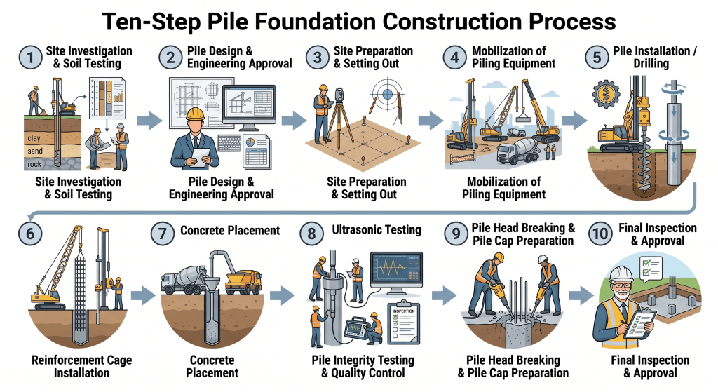
Here’s the sequence a pile foundation actually follows on site, from first site visit to final inspection.
1. Site investigation. A walkover survey, review of existing site records, and identification of access constraints, overhead or underground services, and neighboring structures that might be sensitive to vibration or noise.
2. Soil investigation. Boreholes, Standard Penetration Tests (SPT), cone penetration tests, and sampling for laboratory testing (index properties, shear strength, consolidation characteristics). This is the single most important step in the entire process. Every design decision downstream depends on how accurate and how deep this investigation actually goes.
3. Geotechnical report. The geotechnical engineer interprets the soil data and issues recommendations: pile type, safe bearing capacity at various depths, expected settlement, groundwater conditions, and any special hazards like liquefaction potential or aggressive groundwater chemistry.
4. Layout. The structural engineer sets pile positions, spacing, and cap sizes based on column loads and the geotechnical recommendations, then the survey team sets out the actual pile positions on site.
5. Drilling (or driving). Depending on the chosen pile type, this is either boring with a rotary rig, hammering a precast or steel pile, or torquing a helical pile into position.
6. Reinforcement cage. Fabricated off-site or in a site yard to the design bar schedule, then lowered into a bored pile hole (or, for precast piles, already cast into the unit before delivery).
7. Concreting. Tremie concreting for bored piles below water or drilling fluid, direct pour for dry bores, and quality checks on slump, temperature, and cube samples for every pour.
8. Testing. Integrity testing on a sample of piles (or all piles, depending on spec) and load testing on selected piles, covered in detail further down.
9. Pile cap construction. Excavation to cut-off level, trimming pile heads, fixing reinforcement, formwork, and concreting the cap.
10. Final inspection. As-built survey confirming pile positions match the design layout within tolerance, review of all test results, and sign-off before the structure loads the foundation.
Pile Foundation Details
Typical reinforcement: longitudinal bars are usually sized as a percentage of the pile’s cross-sectional area (commonly in the range of 0.4% to 0.8% for cast-in-situ piles under normal loading, though seismic zones and heavily loaded piles push this higher), with a minimum number of bars, often six or eight, to maintain a reasonable cage shape and handle transportation and installation stresses. Transverse reinforcement is typically closer-spaced near the pile head (where bending and shear from lateral loads concentrate) and can open up further down the shaft where the pile behaves more like a simple axially loaded column.
Pile spacing: minimum center-to-center spacing is generally taken as around three times the pile diameter for friction piles (to limit overlapping stress zones in the soil) and can be slightly tighter, around 2.5 times diameter, for end-bearing piles, though this always needs to be checked against the specific geotechnical recommendations for the site rather than applied blindly.
Cover: concrete cover to reinforcement in piles is generally more generous than in above-ground elements, since piles sit in direct, permanent contact with soil and groundwater, often in aggressive chemical conditions. Cover requirements typically increase further for piles exposed to sulfate-bearing soils or seawater.
Pile cap connection: the pile head is embedded a nominal distance into the cap (commonly around 75mm, though this varies by project spec), and reinforcement or dowel bars project from the pile into the cap to develop full continuity between the two elements.
Development length: both pile reinforcement extending into the cap and cap reinforcement itself need to extend far enough past critical sections to develop full bond capacity. This is a standard reinforced concrete detailing principle, not something unique to piles, but it’s worth flagging because pile cap sections are often congested, and getting proper development length in a tight, heavily reinforced cap takes careful detailing.
Construction joints: ideally, a pile is cast in one continuous pour. When that’s not possible (equipment breakdown, concrete supply interruption), construction joints need to be properly prepared, with the previous lift’s surface cleaned and, where relevant, treated before the next lift proceeds, and this should be documented as a deviation for the engineer’s review.
Pile Foundation Design Considerations
Designing a pile foundation properly means checking a longer list of things than most people expect. Here’s what actually governs the design in practice.
Safe bearing capacity: the pile’s ultimate capacity, whether from end bearing, skin friction, or both, divided by an appropriate factor of safety (commonly in the range of 2 to 2.5 for static analysis, though the exact figure depends on the design method and the applicable code).
Settlement: both total settlement of the whole structure and, more critically, differential settlement between adjacent pile groups, since it’s differential movement that actually cracks structures, not uniform settlement.
Load combinations: dead load, live load, wind, seismic, and construction-stage loads all need to be checked in combination, not just individually, since the governing case for pile capacity isn’t always the same as the governing case for the superstructure above.
Lateral load: wind, seismic action, and, for retaining or waterfront structures, earth or water pressure all impose horizontal forces the pile group needs to resist through a combination of pile bending stiffness and passive soil resistance.
Negative skin friction: happens when the soil around a pile settles more than the pile itself, dragging downward on the shaft instead of supporting it. This adds load to the pile rather than relieving it, and it’s a common problem where piles pass through recently placed fill or soft compressible clay that’s still consolidating.
Pile group effect: piles installed close together don’t behave the same as an isolated single pile; their zones of stress influence overlap in the surrounding soil, generally reducing the group’s overall capacity (and increasing settlement) compared to the simple sum of individual pile capacities. Group efficiency factors account for this in design.
Scour: relevant mainly for bridge piers and river or marine structures, where flowing water erodes soil around the pile over time, effectively reducing the pile’s embedded length and its lateral support. Piles in scour-prone locations are typically designed assuming the scour depth has already occurred, not as a future risk.
Liquefaction: in seismic zones, loose saturated sand can temporarily lose almost all its shear strength during strong ground shaking, and a pile relying on friction through that layer can lose capacity right when the structure needs it most. Liquefaction potential needs its own dedicated geotechnical assessment in earthquake-prone regions.
Groundwater: affects everything from construction method (dewatering, casing, or drilling fluid needs) to long-term durability (sulfate attack, chloride ingress) to uplift forces on basement and marine structures.
How Deep Should Pile Foundations Be?
There’s no fixed depth for pile foundations. It depends entirely on where competent bearing soil or rock is found, how deep the water table sits, and how much load the structure applies. In practice, residential piles often run 6 to 15 meters, mid-rise commercial buildings 15 to 30 meters, and high-rise or bridge piles can exceed 40 to 60 meters where the bearing stratum sits deep.
The depth decision hinges on a few factors working together, not any single one:
Soil profile. The single biggest driver. If dense sand or rock sits at 8 meters, that’s roughly where the pile toe wants to land (with some embedment into the bearing layer itself). If the site is thick soft clay all the way to 40 meters, the design shifts toward a friction pile and depth gets driven by required capacity rather than by hitting a hard layer.
Building load. Heavier structures need either deeper piles reaching stronger strata, larger diameter piles, or more piles in the group. Depth alone isn’t the only lever, but it’s often the most efficient one when a strong layer is within reasonable reach.
Groundwater. A high water table doesn’t necessarily change required depth, but it changes construction method significantly (casing, drilling fluid, dewatering) and affects long-term durability design.
Hard strata / rock depth. Where rock or a very dense layer sits close to the surface, piles are often shorter and rely heavily on end bearing. Where rock is very deep or absent within a practical drilling range, friction piles become the more economical choice even if they need to go deep to develop enough shaft resistance.
| Application | Typical Pile Depth Range | Governing Factor |
|---|---|---|
| Residential (2-3 story) | 6-15 m | Reaching firm soil below fill/weak topsoil |
| Commercial (mid-rise) | 15-30 m | Bearing capacity for moderate column loads |
| High-rise buildings | 25-50+ m | Heavy concentrated loads, settlement control |
| Bridge piers | 20-45 m | Scour depth, lateral load, bearing stratum |
| Marine/offshore structures | 25-60+ m | Wave/current loading, deep soft marine clay |
Nobody should treat these ranges as design values. They’re a sense-check, not a substitute for a proper geotechnical investigation and pile capacity calculation specific to the site.
Pile Load Testing
Testing confirms that a pile actually performs the way the design assumed it would, and it’s not optional on any project where the consequences of a foundation failure are serious, and frankly, that’s every project.
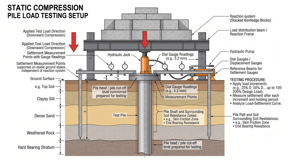
Static Load Test (SLT): the most direct and reliable method. A known load is applied to the pile head, incrementally, using a hydraulic jack reacting against either kentledge (dead weight) or anchor piles, while settlement is measured at each stage. It’s slow (can take days) and expensive relative to other methods, but it’s the benchmark other tests get calibrated against.
Dynamic Load Test: applies a large impact force to the pile head (typically via a drop hammer) and measures the resulting stress wave using strain gauges and accelerometers, then interprets pile capacity through wave equation analysis. Much faster and cheaper than a static test, and useful for testing a larger sample of piles on a project, though it relies more heavily on interpretation and correlation than a static test does.
Pile Integrity Test (PIT) / Low Strain Test: a small hammer strikes the pile head and a sensor records the resulting stress wave reflections, revealing defects like necking, cracking, or voids along the shaft length. Fast, non-destructive, and cheap enough to run on every pile on a project, which is exactly why it’s become close to standard practice for cast-in-situ piles.
High Strain Test: essentially the dynamic load test described above, sometimes listed separately in specifications; it uses a much larger impact energy than the low strain test and is aimed at capacity verification rather than just integrity/defect detection.
Cross Hole Sonic Logging (CHSL): used specifically on large-diameter bored piles with pre-installed access tubes cast into the pile. Ultrasonic signals are sent between tubes at increasing depth, and any weak or void zones show up as delayed or attenuated signals. This is the most thorough integrity check available for bored piles and is often specified for critical, heavily loaded piles.
Acceptance criteria vary by test and by project specification, but generally: static and dynamic load tests need to demonstrate the pile carries the design load (often at some multiple, like 1.5 to 2 times working load) without exceeding a specified settlement limit and without excessive residual (non-recoverable) settlement after load removal. Integrity tests are judged against a “typical” clean signal for that pile length and diameter, with any anomaly flagged for further investigation rather than an automatic pass/fail.
| Test Method | Speed | Cost | Primary Purpose | Destructive? |
|---|---|---|---|---|
| Static Load Test | Slow (days) | High | Capacity verification (benchmark method) | No |
| Dynamic Load Test | Fast (hours) | Moderate | Capacity verification, larger sample size | No |
| Pile Integrity Test (Low Strain) | Very fast (minutes) | Low | Shaft defect detection | No |
| High Strain Test | Fast (hours) | Moderate | Capacity verification | No |
| Cross Hole Sonic Logging | Moderate | Moderate-High | Detailed integrity check on large bored piles | No |
Advantages of Pile Foundations
- Transfers load through weak surface soil to a stronger bearing stratum, when a shallow footing simply can’t.
- Handles heavy concentrated loads from high-rise columns or industrial equipment.
- Controls total and differential settlement far better than a shallow foundation on poor soil.
- Works below the water table without the same construction difficulty a large excavated footing would face.
- Resists uplift forces effectively, particularly with under-reamed or belled piles.
- Provides good lateral load resistance for wind and seismic forces when properly designed.
- Adaptable to a wide range of soil conditions, from soft marine clay to dense gravel.
- Reduces the footprint needed at the surface compared to a very large spread footing on weak soil.
- Precast options offer strong quality control since manufacturing happens off-site.
- Bored options minimize noise and vibration, useful near sensitive existing structures.
- Helical and screw piles install quickly with no curing time and minimal spoil.
- Suitable for both permanent structures and, in the case of helical piles, temporary or relocatable ones.
- Can be tested individually to confirm capacity before the structure is loaded, reducing risk.
- Works well for underpinning existing foundations that have settled or need additional capacity.
- Performs reliably in marine and waterfront environments where other foundation types struggle.
- Reduces risk from scour at bridge piers by extending well below the anticipated scour depth.
- Long service life when properly designed for durability and protected against corrosion or sulfate attack.
Disadvantages of Pile Foundations
- Higher initial cost than a shallow foundation on soil that could otherwise support one.
- Requires specialized equipment and a skilled crew, which limits contractor availability in some regions.
- Driving generates noise and vibration that can disturb neighbors or affect nearby structures.
- Quality of cast-in-situ piles is harder to verify visually than a precast or driven unit.
- Poor workmanship (inadequate base cleaning, concreting defects) can seriously compromise capacity.
- Ground obstructions like boulders or old foundations can stop driven piles or damage equipment.
- Negative skin friction can add unexpected load in sites with settling fill or soft consolidating clay.
- Group effects reduce capacity and increase settlement compared to isolated pile behavior, and this needs careful analysis.
- Testing, particularly static load tests, adds time and cost to the project schedule.
- Design requires a thorough, often expensive, soil investigation to avoid over- or under-design.
- Piles in aggressive soil or seawater need extra durability measures, adding cost.
- Steel piles are vulnerable to long-term corrosion without proper protection.
- Remediation of a defective pile after concreting is difficult and expensive compared to fixing a shallow foundation issue.
- Vibration from driven piles can densify or disturb soil around adjacent, already-completed piles.
- Mobilization cost for piling rigs can make small jobs disproportionately expensive.
- Access constraints on tight urban sites can rule out larger rigs, limiting pile type and diameter options.
- Environmental and regulatory restrictions on noise, vibration, and groundwater impact can complicate scheduling and method selection.
Applications
Pile foundations show up across nearly every heavy or ground-sensitive construction sector:
- Buildings: high-rises, commercial towers, and any structure on soft or variable soil.
- Bridges: pier and abutment foundations, particularly over water or deep alluvial deposits.
- Towers: transmission towers, telecom masts, and wind turbines, where uplift and lateral load matter as much as vertical load.
- Marine structures: jetties, quays, wharves, and offshore platforms.
- Factories: heavy machinery foundations needing both capacity and vibration control.
- Hospitals: critical facilities where settlement control and long-term reliability are non-negotiable.
- Airports: terminal buildings and, in some cases, runway structures over poor subgrade.
- Power plants: foundations for turbines, boilers, and cooling towers carrying large static and dynamic loads.
- Oil & gas: tank farms, process structures, and pipeline supports, often in coastal or reclaimed land settings.
- Ports: berths, container yard pavements, and crane rail foundations subject to heavy repetitive loading.
- Dams: cutoff walls and ancillary structure foundations, sometimes using sheet piles for seepage control.
Raft Foundation vs Pile Foundation
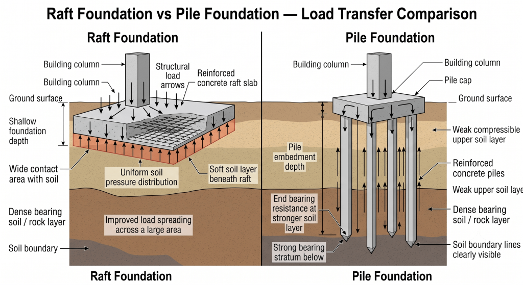
This is one of the most common foundation decisions engineers face on medium-load sites with moderately poor soil, and the honest answer is that it depends on the numbers, not a rule of thumb. Here’s how the two compare across the factors that actually drive the decision.
| Factor | Raft Foundation | Pile Foundation |
|---|---|---|
| Cost | Lower for moderate loads on reasonable soil | Higher initial cost, especially with deep piles |
| Construction speed | Generally faster, less specialized equipment | Slower, needs mobilization of piling rigs |
| Depth | Shallow, near-surface | Deep, extends to bearing stratum |
| Bearing capacity | Limited by soil directly beneath the raft | Can access much stronger soil/rock at depth |
| Settlement | Can be significant on soft or variable soil | Better controlled, especially for heavy loads |
| Suitable soil | Reasonably competent, fairly uniform soil | Soft, weak, variable, or deep poor soil |
| Maintenance | Low, once constructed | Low, but harder to inspect/repair if issues arise |
| Applications | Low-to-mid rise buildings on decent soil | High-rise, bridges, marine structures, poor soil sites |
| Service life | Long, if soil conditions are stable | Long, generally very durable when properly designed |
| Advantages | Economical, simple, spreads load over large area | Handles heavy loads, poor soil, deep water tables |
| Disadvantages | Large differential settlement risk on variable soil | Higher cost, specialized equipment and expertise needed |
| Recommendation | Use where soil is reasonably strong and loads are moderate | Use where soil is weak, loads are heavy, or settlement tolerance is tight |
A middle path worth knowing about: the piled raft, where a raft foundation is supported by a limited number of settlement-reducing piles rather than either a full raft alone or a full pile group. It’s increasingly common for mid-to-high-rise buildings on soil that’s not quite bad enough to justify a full pile foundation but not quite good enough for a raft alone.
IS Code for Pile Foundation
Indian Standard codes provide the governing framework for pile design and construction across India and, informally, across much of South Asia and the Gulf where Indian consulting practice has strong influence. Here’s what each relevant code actually covers, in plain language, without reproducing any clause text:
IS 2911 (All Parts): the primary code dealing specifically with design and construction of pile foundations. It’s split across several parts covering different pile types: driven cast-in-situ concrete piles, bored cast-in-situ concrete piles, driven precast concrete piles, bored precast concrete piles, timber piles, and under-reamed piles, plus a part addressing load testing procedures.
IS 456: the general code for plain and reinforced concrete design, which pile design leans on for concrete mix requirements, reinforcement detailing principles, and durability provisions relevant to any concrete element, piles included.
IS 6403: addresses bearing capacity calculation methods for shallow foundations, but the underlying soil mechanics principles it establishes (particularly around shear strength parameters) feed into deep foundation capacity calculations as well.
IS 1893: the seismic design code for structures, relevant to pile foundations because it sets out the earthquake load combinations and ductile detailing philosophy that pile and pile cap design need to satisfy in seismic zones.
IS 875: covers design loads for buildings, including dead load, live load, wind load, and snow load provisions that feed directly into the load combinations used for pile capacity checks.
IS 1786: specifies the standard for high-strength deformed steel bars used as reinforcement, relevant to selecting and specifying the reinforcement grade used in pile cages and pile caps.
BS Code for Pile Foundation
British Standards and their Eurocode successors govern pile design and construction across the UK and, by extension, much of the Gulf region, where BS and Eurocode practice remains widely used alongside IS code practice. Here’s what each covers:
BS EN 1997 (Eurocode 7): the geotechnical design code covering the overall framework for foundation design, including piles, with its partial factor approach to combining loads and soil resistance, replacing the older BS 8004 approach to allowable stress design in most current UK and European practice.
BS EN 1536: specifically addresses execution of bored piles, covering construction methods, materials, tolerances, and quality control requirements for the boring, reinforcement, and concreting process.
BS EN 12699: covers execution of displacement piles (the driven pile category), addressing installation methods, equipment, and verification requirements distinct from the bored pile provisions in BS EN 1536.
BS 8004: the older British Standard for foundations, largely superseded by Eurocode 7 in current design practice but still referenced on many older projects and still a useful source for foundational geotechnical principles even where it’s no longer the primary design code.
Common Problems in Pile Foundations
Pile deviation: the pile drifts out of its intended vertical or positional alignment during installation, often from hitting an obstruction or from equipment not being properly plumbed. Minor deviation is usually accommodated in design tolerances; significant deviation can require redesign of the pile cap or an additional pile.
Pile cracking: can occur during handling and driving of precast piles (tension cracks from bending while lifting) or from excessive driving stress. Cast-in-situ piles can crack from ground movement or from inadequate curing before load is applied.
Necking: a reduction in pile cross-section at some point along its length, typically in bored piles where soft or squeezing ground presses inward on fresh concrete before it sets, or where casing is withdrawn too early. Integrity testing is specifically good at catching this.
Honeycombing: porous, poorly compacted concrete with visible voids, usually from inadequate flow, incorrect mix design, or reinforcement congestion blocking proper concrete placement.
Pile uplift: occurs when a pile is subjected to net upward force exceeding its resistance, from hydrostatic pressure, expansive soil movement, or structural loading (like wind uplift on a tall, light structure). Under-reamed or belled piles and adequate reinforcement for tension are the usual remedies.
Settlement: excessive settlement, whether from underestimated load, overestimated soil capacity, or pile group effects not properly accounted for in design.
Negative skin friction: covered earlier, but worth repeating here as a “problem” category since it’s frequently underestimated in preliminary design and only becomes obvious once fill or soft clay around the pile actually starts consolidating.
Groundwater issues: can prevent proper concrete placement, cause pile shaft washout during construction, or lead to long-term durability issues if not properly designed against.
Construction errors: inadequate base cleaning, wrong pile depth, reinforcement cage displacement during concreting, and poor record-keeping that makes later problems harder to diagnose.
Remedial measures: depending on the defect, options include additional piles to share load, underpinning, grouting to fill voids, jacket or casing repair for exposed marine piles, or, in severe cases, full pile replacement.
Inspection Checklist
Before installation:
- Confirm geotechnical report matches actual site conditions observed during mobilization.
- Verify pile positions are correctly set out and match the foundation layout drawing.
- Check equipment calibration (torque monitoring for helical piles, hammer energy for driven piles).
- Confirm reinforcement cage fabrication matches the approved bar bending schedule.
- Review method statement and confirm any nearby structures needing vibration monitoring.
During installation:
- Record depth, torque, or driving resistance continuously against the design criteria.
- Confirm base cleanliness before concrete placement (for bored piles).
- Monitor concrete volume placed against theoretical volume during pour.
- Check tremie pipe embedment depth is maintained throughout the pour.
- Log any obstructions, deviations, or anomalies as they occur, not after the fact.
After installation:
- Verify pile cut-off level against design.
- Schedule and review integrity test results for every pile, or the specified sample.
- Confirm load test results (where required) before proceeding to pile cap construction.
- Cross-check as-built pile positions against the design layout, flagging any deviation beyond tolerance.
- Compile and file complete construction records before pile caps cover the pile heads.
Maintenance and Repair
Pile foundations are largely maintenance-free once properly constructed and buried, but a few situations call for ongoing attention, particularly for marine and exposed piles.
Inspection of exposed piles (marine jetties, piers) should happen on a regular schedule, checking for corrosion on steel piles, spalling or cracking on concrete piles, and marine growth or impact damage from vessels.
Monitoring of settlement, particularly for structures on friction piles in consolidating soil, helps catch a developing problem long before it becomes visible as structural distress.
Repair methods range from patching spalled concrete and applying protective coatings, to jacketing (wrapping a deteriorated pile in a new concrete or composite shell), to cathodic protection systems for steel piles in marine environments.
Strengthening of an existing pile foundation, when loads increase beyond original design capacity, typically involves adding new piles tied into the existing pile cap or constructing a new, larger cap incorporating both old and new piles.
Underpinning addresses settled or inadequate existing foundations by installing new piles (often micropiles or helical piles, given restricted access under an existing structure) beneath or beside the original foundation and transferring load onto them.
Retrofit techniques for seismic upgrading can include additional piles for lateral capacity, improved pile-to-cap connections, or soil improvement around the existing pile group to reduce liquefaction risk.
Cost Factors
Pile foundation cost varies enormously by project, but the factors driving that variation are fairly consistent:
- Soil conditions: harder driving, deeper required depths, or the need for casing and drilling fluid all add cost.
- Pile type: driven precast piles are often cheaper per unit length than large-diameter bored piles, but the right choice depends on site constraints, not just unit cost.
- Diameter: larger diameter piles cost more per meter but carry more load, so the real comparison is cost per unit of capacity, not cost per meter.
- Depth: deeper piles mean more material, more time, and often larger equipment.
- Equipment: mobilization of a large piling rig to a remote or difficult-access site can be a significant fixed cost regardless of the number of piles.
- Concrete: mix design, especially for durability in aggressive ground, and the volume actually placed (which can exceed theoretical volume in loose or caving soil).
- Steel: reinforcement quantity and, for steel piles, the raw material cost, which fluctuates with global steel prices.
- Labor: skilled piling crews are not universally available, and labor cost varies significantly by region and by how specialized the pile type is.
- Testing: static load tests in particular add real cost and schedule time, though skipping adequate testing is a false economy given what’s at stake.
- Location: site access, ground conditions, and local labor/equipment availability can shift total pile foundation cost more than any single technical factor.
Frequently Asked Questions
What is a pile foundation? A pile foundation is a deep foundation system using long structural elements driven or bored into the ground to transfer building loads through weak surface soil to a stronger bearing layer, or to soil offering sufficient friction resistance.
How deep should pile foundations be? Depth depends on soil profile, groundwater, and building load rather than a fixed number, but residential piles often run 6-15 meters, commercial buildings 15-30 meters, and high-rise or bridge piles can exceed 40-60 meters.
What is the difference between pile and raft foundation? A raft foundation is a shallow, wide slab spreading load over the soil directly beneath it, while a pile foundation transfers load deep down to a stronger stratum, making piles the better choice on weak or highly variable soil.
What is a bored pile? A bored pile is formed by drilling a hole into the ground, placing a reinforcement cage, and filling it with concrete in place, rather than driving a pre-manufactured pile into the soil.
What is a helical pile? A helical pile is a steel shaft fitted with helix-shaped bearing plates that’s rotated into the ground using hydraulic torque, providing immediate load capacity confirmation through the torque required for installation.
What is a screw pile? A screw pile works on the same rotational installation principle as a helical pile, though the term is sometimes used specifically for continuous-helix or smaller marine and residential screw-in foundation elements.
What is a pile cap? A pile cap is a reinforced concrete slab sitting on top of one or more piles, distributing the column or wall load evenly across the pile group beneath it.
What is IS 2911? IS 2911 is the Indian Standard covering design and construction of pile foundations, split across parts addressing different pile types including driven and bored, cast-in-situ and precast concrete piles, timber piles, and under-reamed piles.
Which foundation is best for soft soil? Pile foundations are generally the better choice for soft soil, since they bypass the weak surface layer entirely and transfer load to a stronger stratum at depth, avoiding the excessive settlement a shallow foundation would experience.
How long do pile foundations last? Properly designed and constructed pile foundations, particularly concrete piles with adequate cover and durability provisions, can last well beyond 50-100 years, though steel piles need corrosion protection to achieve similar service life in aggressive environments.
What is the difference between end-bearing and friction piles? End-bearing piles transfer most of their load through the pile toe to a hard stratum, while friction piles rely primarily on skin resistance along the shaft in soil with no accessible hard layer within practical reach.
What is pile integrity testing? Pile integrity testing (low strain testing) uses a small hammer impact and sensor readings to detect defects like necking, cracking, or voids along a pile’s shaft, without needing to load the pile to failure or expose it physically.
What is an under-reamed pile? An under-reamed pile has one or more bulb-shaped enlargements formed at the base (or at intervals along the shaft), increasing bearing area and uplift resistance, commonly used in expansive clay soils and for structures needing extra tension capacity, like transmission towers.
What is a micropile foundation? A micropile is a small-diameter (generally under 300mm), drilled and grouted pile, used where access is restricted, such as underpinning an existing foundation or working inside a building with low headroom.
What is negative skin friction? Negative skin friction happens when soil around a pile settles more than the pile itself, dragging downward along the shaft and adding load to the pile instead of supporting it, common where piles pass through recently placed fill.
What causes necking in bored piles? Necking usually happens when soft or squeezing ground presses inward on freshly placed concrete before it sets, or when temporary casing is withdrawn too early during concreting.
What is the minimum spacing between piles? Minimum center-to-center spacing is generally around three times the pile diameter for friction piles and slightly tighter for end-bearing piles, though the exact figure should always come from project-specific geotechnical recommendations.
Can pile foundations be used for residential houses? Yes, particularly on soft, expansive, or fill soil, where shallow footings would settle unevenly. Helical piles have become a popular residential option because of fast, low-disturbance installation.
What is a driven pile foundation? A driven pile foundation uses precast concrete, steel, or timber piles hammered, vibrated, or pushed into the ground, displacing soil outward as they advance, rather than removing soil through drilling.
What is the difference between driven and bored piles? Driven piles displace soil and install quickly but generate noise and vibration, while bored piles remove soil through drilling first, working more quietly and adapting more easily to variable ground, though with more demanding quality control.
What is a sheet pile used for? Sheet piles are interlocking sections driven side by side to form a continuous wall, used for retaining soil, cofferdams for dry excavation, and riverbank or coastal erosion protection.
How is pile capacity determined? Pile capacity is determined through geotechnical calculation methods based on soil parameters, then verified in the field through static or dynamic load testing on selected piles.
What is a pile load test? A pile load test applies a known load (statically, through a hydraulic jack, or dynamically, through impact) to a pile and measures its response, confirming the pile performs at or above its design capacity.
Why are pile caps needed? Pile caps tie individual piles together into a group acting as one unit, distributing column loads evenly across every pile and providing a level connection point for the structure above.
What is the difference between BS 8004 and Eurocode 7? BS 8004 is the older British Standard for foundation design using an allowable stress approach, while Eurocode 7 (BS EN 1997) uses a partial factor design approach and has largely replaced BS 8004 in current UK and European practice.
Do pile foundations need maintenance? Buried pile foundations generally need little to no maintenance, but exposed piles, particularly marine and waterfront piles, benefit from periodic inspection for corrosion, spalling, or physical damage.
Conclusion
Pile foundations exist to solve one specific problem: getting a structure’s load safely down to soil or rock that can actually carry it, when the ground near the surface can’t do the job on its own. Everything else in this guide, the material choices, the installation methods, the code references, the testing regime, all of it exists in service of that one goal.
The right pile type depends entirely on what the geotechnical investigation actually finds. Driven piles suit sites where speed and displacement benefits matter and vibration isn’t a concern. Bored piles suit congested urban sites and large-diameter, high-capacity requirements. Helical and screw piles suit fast, low-disturbance installation on lighter structures and restricted-access sites. There’s no universal “best” pile, only the right pile for the soil, the load, and the site constraints in front of you.
If there’s one habit that separates a good pile foundation project from a troubled one, it’s respecting the soil investigation. Every design assumption, every capacity calculation, every depth decision traces back to that data. Skimp on it, and no amount of careful pile cap detailing downstream will save the project from an expensive surprise.
For anyone specifying or reviewing a pile foundation design, the practical takeaways are straightforward: get a proper geotechnical investigation before committing to a pile type, match the pile type to the actual site constraints rather than defaulting to whatever’s familiar, detail the pile cap and reinforcement with the same care as the piles themselves, and never treat testing as an optional line item, because it’s the only real confirmation that the foundation will do exactly what the design says it will.