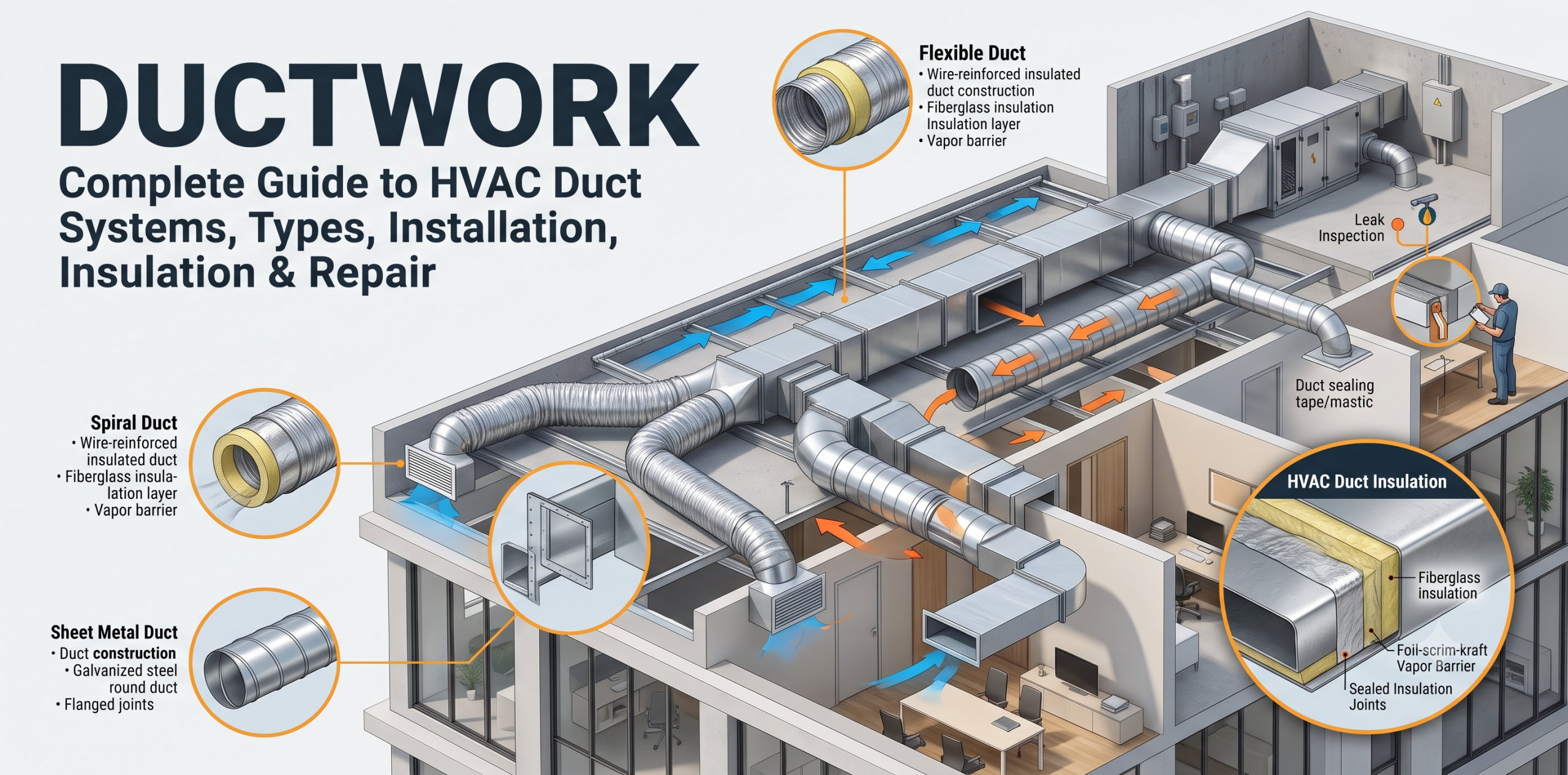
Most people never think about ductwork until something goes wrong. A room that never gets cool enough. A rattling noise every time the furnace kicks on. A musty smell drifting out of a supply grille. Nine times out of ten, the problem traces back to the duct system, not the equipment bolted to it.
That’s the part people miss. A high-efficiency heat pump or a brand-new AHU can only perform as well as the ductwork carrying its air. Undersized returns choke the fan. Leaky joints in an attic dump conditioned air where nobody can use it. Flex duct crushed behind a ceiling grille cuts CFM in half without anyone noticing until the electric bill arrives. Ductwork is the circulatory system of a building, and like any circulatory system, a blockage or a leak anywhere along the line shows up somewhere else entirely.
This guide walks through what ductwork actually is, how air moves through it, the materials and shapes in common use, how it’s sized and installed, and where it tends to fail. It’s written for homeowners trying to understand a quote from a contractor, technicians who want a quick reference, and engineers or quantity surveyors who need the standards and numbers behind the design decisions.
What is Ductwork?
Ductwork is the network of enclosed pathways, usually metal, fiberglass, or flexible plastic and wire composite, that carries air between an HVAC unit and the spaces it conditions. It sounds simple. In practice, it’s one of the most misunderstood parts of a building’s mechanical system, mostly because it’s invisible once the ceiling goes up.
For a homeowner, the easiest way to picture it: your furnace or air handler is the heart, and ducts are the arteries and veins. Supply ducts push warm or cool air out to each room. Return ducts pull air back to the unit so it can be filtered, conditioned again, and recirculated. Without a return path, the supply air has nowhere to go, and the whole system starves for air.
For an engineer or contractor, the definition carries more weight. Ductwork has to be sized for a specific airflow rate (measured in CFM, cubic feet per minute), matched to the static pressure the fan can overcome, and routed to avoid excessive friction loss. Get the sizing wrong and you end up with one of two failure modes: ducts too small create noise and high velocity that wastes fan energy, while ducts too large drop velocity so low that air barely reaches the far end of a run.
Supply and return ducts aren’t interchangeable, even though they can look identical from the outside. Supply ducts are typically smaller and run at higher velocity since they’re delivering conditioned air directly to a room. Return ducts are usually larger, since they’re collecting air from multiple rooms and moving it back at lower velocity to reduce noise near occupied spaces. A duct system with an undersized return is one of the most common design mistakes on residential jobs, and it’s often the reason a system “just never feels right” even though the equipment itself is fine.
Good duct design isn’t just about moving air from point A to point B. It affects comfort (even temperatures room to room), energy use (leaky or poorly insulated ducts waste 20% or more of conditioned air in some homes), noise levels, and indoor air quality.
How HVAC Ductwork Works
Here’s the full path air takes through a typical forced-air system:
AHU → Supply Duct → Diffuser/Grille → Conditioned Space → Return Grille → Return Duct → Filter → AHU
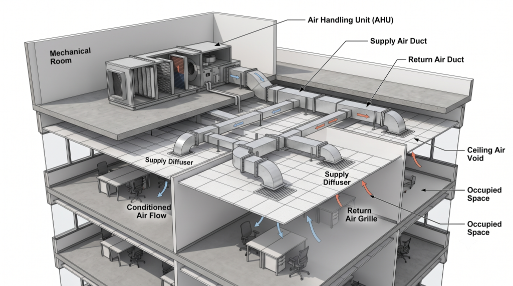
The air handling unit (AHU) contains the blower, the coil (evaporator or heating element), and often the filter rack. The blower is the engine of the whole system: it has to generate enough static pressure to push air through every duct, fitting, elbow, and diffuser between it and the room.
Conditioned air leaves the AHU through the supply trunk, a main duct that branches off into smaller runs feeding individual rooms. Each branch terminates at a diffuser or grille, the visible outlet in a ceiling, wall, or floor. Diffuser selection matters more than most people realize. The wrong throw pattern or a mismatched neck size creates drafts or dead zones even when the CFM delivered is technically correct.
Once air has done its job in the room, it needs a way back. That’s the return side: grilles pull room air into the return duct, which routes it back to the AHU. On the way, it passes through a filter (removing dust and particulates before the coil gets dirty), then across the coil to be reheated or recooled, and the cycle repeats.
Static pressure is the resistance the fan has to overcome across this whole loop, filter, coil, ducts, fittings, and diffusers included. Most residential air handlers are rated for around 0.5 in. w.c. of total external static pressure. Undersized ducts, a dirty filter, or too many sharp elbows can push actual static pressure well past that, which cuts airflow, increases energy use, and shortens the life of the blower motor.
Types of Ductwork
Different projects call for different duct types, and the choice usually comes down to space constraints, budget, airflow requirements, and whether the run is exposed or concealed.
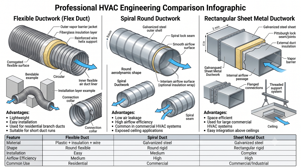
| Type | Material | Advantages | Disadvantages | Applications |
|---|---|---|---|---|
| Rectangular sheet metal | Galvanized steel, aluminum | Rigid, durable, fits tight spaces above ceilings, easy to insulate externally | More joints and seams (higher leakage risk), heavier, slower to fabricate and install | Commercial buildings, large residential trunks, industrial plants |
| Spiral round duct | Galvanized steel, aluminum | Fewer seams, lower leakage, lower friction loss, faster install with pre-fabricated fittings, cleaner look if exposed | Round shape doesn’t fit flush against ceilings as easily, can cost more per linear foot for small runs | Offices, restaurants, retail fit-outs, exposed-ceiling designs |
| Flexible duct (flex duct) | Wire helix core, plastic liner, fiberglass insulation, vapor barrier jacket | Fast installation, flexible around obstructions, good acoustic damping, lower material cost | Higher friction loss if not pulled taut, prone to crushing and sagging, shorter lifespan (10-15 years typical) | Residential branch runs, tight attic and crawlspace routing |
| Fiberglass duct board | Rigid fiberglass board with foil facing | Built-in insulation, quiet, lightweight | Interior surface can degrade or grow mold if wet, less durable than metal, phased out in some jurisdictions | Residential trunk and branch, light commercial |
| Fabric duct | Woven textile (polyester) | Even air dispersion, lightweight, good for large open spaces, custom shapes | Not suited to high static pressure, requires specific hanging hardware, higher upfront cost per linear foot | Gyms, warehouses, retail spaces with exposed ceilings |
Sheet Metal Ductwork
Galvanized steel is still the default material for commercial HVAC ductwork, mostly because it’s fire-resistant, structurally rigid, and holds up for decades with minimal maintenance. Aluminum ducts show up where weight matters, kitchen exhaust runs and some marine or aerospace-adjacent applications, since aluminum is lighter but more prone to denting.
Fabrication follows a fairly standard process: sheet stock gets cut to size, formed into rectangular or round sections on a brake or duct machine, and joined using seams like Pittsburgh lock or snap lock. Larger commercial jobs are often fabricated off-site in a shop and shipped to the field as pre-cut sections, which speeds installation and improves seam quality compared to field fabrication.
Spiral Ductwork
Spiral round duct is manufactured by feeding metal coil stock through a spiral forming machine that locks the seam continuously along the length of the duct, rather than joining flat sections with separate seams every few feet. That single continuous seam is the whole reason spiral duct performs the way it does.
The advantages show up in three places. First, leakage: fewer seams means fewer places for air to escape, so spiral duct systems routinely test tighter than rectangular sheet metal without extra sealing effort. Second, airflow: the round cross-section has less surface friction than a rectangular duct carrying the same CFM, which lowers the fan energy needed to move the same volume of air. Third, install speed: pre-manufactured fittings (elbows, tees, reducers) snap together faster than field-fabricated rectangular transitions.
Spiral duct has also become a design element in its own right. Exposed spiral runs painted black or left in raw galvanized finish are common in restaurants, offices, and retail spaces going for an industrial look, which is part of why it’s shown up more in commercial fit-outs over the last decade.
Flexible Ductwork / Flex Duct
Flexible ductwork, or flex duct, is built in layers: a wire helix gives it shape and lets it bend, a plastic inner liner (usually polyester or PVC) forms the airtight core, a fiberglass insulation layer wraps around that, and an outer vapor barrier jacket seals the whole assembly against moisture.
The upside is speed and flexibility, literally. A flex run can snake around framing, plumbing stacks, and structural obstacles that would require multiple field-cut elbows in rigid duct. It’s also quieter than metal, since the flexible wall doesn’t transmit fan noise the way sheet metal does.
The downside is that flex duct is unforgiving of bad installation. Every sag, kink, or tight bend adds friction loss that isn’t in anyone’s design calculation. SMACNA guidance calls for flex duct to be pulled reasonably taut, supported at intervals no greater than about 4 feet, and kept to bend radii no tighter than roughly one duct diameter. A flex run crammed into a joist bay with three 90-degree bends can lose half its rated airflow before it ever reaches the register.
6 in flexible ductwork is one of the most common branch sizes in residential work, typically used for individual bedroom or small-room supply runs. At a reasonable design velocity, a 6-inch flex duct handles somewhere in the range of 100 to 130 CFM depending on friction rate assumptions. Manufacturers generally recommend keeping any single flex run under 25 feet where possible, and definitely under 35 feet, since friction loss compounds quickly in a flexible, corrugated interior compared to smooth rigid duct.
HVAC Ductwork Materials
Metal Ductwork
Galvanized steel remains the workhorse material: zinc-coated for corrosion resistance, rigid, and rated for a wide range of duct pressure classes under SMACNA standards. Stainless steel shows up in specific applications, commercial kitchen exhaust, labs, hospitals, anywhere corrosion resistance or cleanability matters more than upfront cost. Aluminum trades some strength for weight savings and is common in flexible connectors, kitchen makeup air, and some spiral duct applications.
Flexible Duct Materials
The inner liner is usually a PVC or polyester film wrapped around the wire helix, forming the actual air barrier. Fiberglass insulation surrounds that liner, typically rated at R-4.2, R-6, or R-8 depending on climate zone requirements. The outer jacket is often an aluminum laminate or reinforced polyethylene vapor barrier, which keeps humid air from migrating into the insulation and causing condensation damage from the outside in.
Fabric Ductwork
Textile air distribution systems are built from engineered polyester fabric, sometimes permeable enough to diffuse air gently across its entire surface rather than through discrete diffusers. They’re common in warehouses, gyms, and any large open commercial space where even air distribution across a wide floor area matters more than a tightly directed throw pattern.
Ductwork Installation Process
HVAC ductwork installation follows a sequence that, when skipped or rushed, is the single biggest source of comfort complaints on a finished job.
- Load calculation. Before any duct gets sized, the heating and cooling load for the building or each room has to be calculated (Manual J for residential, or equivalent commercial load software). Every downstream decision depends on this number.
- Duct design. Using the load calculation, a designer lays out the duct system and sizes each run, typically using the Equal Friction method for residential and light commercial work. Larger commercial systems sometimes use Static Regain for better balance across long runs.
- Airflow calculation. Each branch gets a target CFM based on the room’s load, and duct sizes are selected from a friction chart to hit that CFM without excessive velocity or noise.
- Material selection. Sheet metal, spiral, or flex duct is chosen based on the application, budget, and where the run is located (exposed, in a plenum, in conditioned or unconditioned space).
- Fabrication. Rigid duct sections are cut and formed to the design dimensions, either in a shop or on site.
- Supports and hangers. Ducts are hung using strapping or trapeze hangers at intervals specified by SMACNA (generally every 8 to 10 feet for rectangular metal duct, tighter for flex).
- Connecting duct sections. Sections are joined using slip joints, flanges, or drawbands, depending on duct type and pressure class.
- Sealing joints. Every seam and joint gets sealed, covered in detail in the next section.
- Insulation. Ducts running through unconditioned space get wrapped or lined to prevent energy loss and condensation.
- Air balancing and testing. A test and balance (TAB) technician measures actual airflow at each diffuser and adjusts dampers until delivered CFM matches the design.
A few installation principles apply regardless of duct type: avoid sharp 90-degree turns where a smoother radius elbow would do, keep ducts accessible for future service (especially at dampers and access panels), and treat every joint as a potential leak point until it’s sealed and tested. Proper duct sizing isn’t a one-size-fits-all number pulled from a chart. It has to match the actual load and the actual fan curve of the equipment installed, or the whole system fights itself.
Ductwork Insulation Guide
Ductwork insulation exists for four reasons: energy efficiency, condensation prevention, noise reduction, and temperature control.
Uninsulated ductwork running through an attic, crawlspace, or unconditioned garage loses (or gains) heat constantly. In a hot climate, an uninsulated supply duct running through a 130°F attic can pick up enough heat that cool air actually warms several degrees before it reaches the register. In a cold climate, the reverse happens. Either way, the equipment has to work harder to compensate, and the energy cost shows up on every utility bill for the life of the system.
Condensation is a separate but related problem. Cold supply ducts running through warm, humid space can drop below the dew point of the surrounding air, causing moisture to form on the duct’s outer surface. Over time, that moisture soaks into ceiling drywall or insulation, and it’s one of the more common causes of hidden water damage in humid climates.
Wrap Insulation Ductwork
Wrap insulation ductwork typically means fiberglass duct wrap applied to the exterior of rigid metal duct. It comes faced with a foil or FSK (foil-scrim-kraft) vapor barrier on one side, which has to face outward, away from the duct metal, to stop humid ambient air from reaching the cold duct surface and condensing.
Thickness selection depends on climate zone and application: R-6 is a common minimum for ducts in unconditioned attics in most residential codes, though R-8 shows up in colder zones or for extended runs. Installation matters as much as the R-value chosen. Wrap has to be installed without compressing the insulation (compression kills R-value), seams need to be taped, and the vapor barrier has to be continuous, since a gap is where condensation starts.
Internal duct insulation, typically fiberglass duct liner adhered to the inside of sheet metal duct, serves a slightly different purpose. It adds acoustic damping (useful right at the AHU discharge, where fan noise is loudest) in addition to some thermal resistance, but it’s fallen out of favor in some jurisdictions over air quality concerns, since a damaged or wet liner surface is harder to clean than a smooth interior wall.
Ductwork Tape and Sealing
Ductwork Tape
Ductwork tape is one of the most misunderstood products in the industry, mostly because of its name. Standard cloth “duct tape,” the silver stuff sold in every hardware store, is not rated for permanent HVAC duct sealing. Its adhesive dries out and fails within a few years under the heat cycling ductwork experiences, and it doesn’t meet UL 181 standards for HVAC applications. It’s fine for a temporary fix on a cardboard box. It’s the wrong material for a joint that needs to hold for the next twenty years.
The actual products used in duct sealing are:
- Aluminum foil tape, rated UL 181A-P, used on rigid duct joints and seams.
- Mastic sealant, a paintable, flexible compound rated UL 181A-M, applied by brush or trowel over seams, joints, and any place a mesh reinforcement (like fiberglass mesh tape embedded in mastic) is used for extra strength.
Sealing needs to happen at every transverse joint (where duct sections connect end to end), every longitudinal seam (the seam running the length of a duct section), and at every takeoff where a branch connects to the trunk. These connection points are where the vast majority of duct leakage happens, not through the flat sides of the duct itself. On a poorly sealed system, leakage at these joints alone can account for 20 to 30% of total airflow, air that’s paid for but never reaches a room.
Ductwork CFM Chart
This ductwork CFM chart gives commonly used design ranges for round duct sizes at typical residential design velocities. Actual capacity depends on the friction rate and velocity assumptions used in the design, so treat these as a reference starting point, not a substitute for a proper duct calculation.
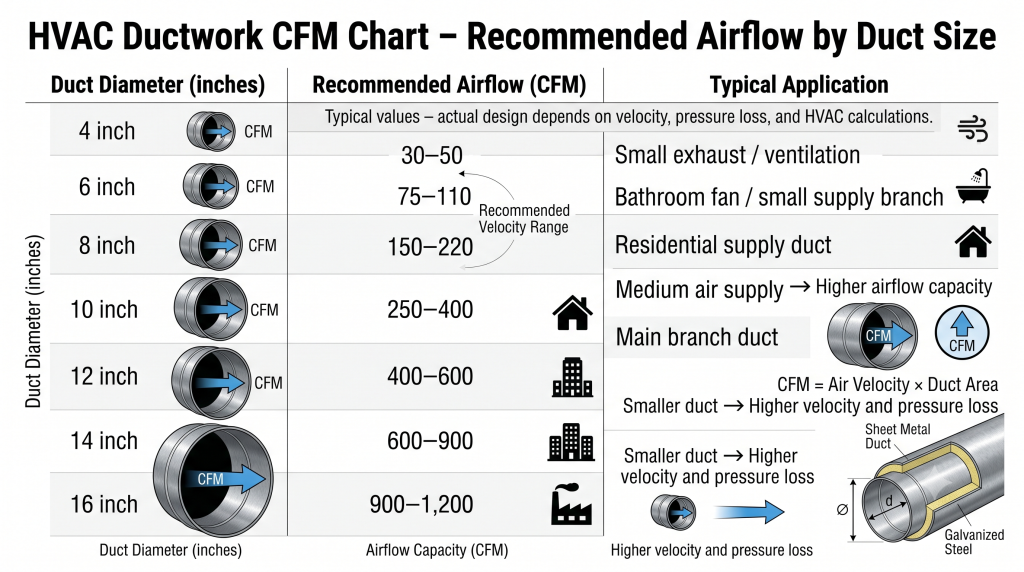
Duct size and airflow are directly related through velocity: for a given CFM, a larger duct moves air more slowly, which means less friction loss and less noise, but costs more material and takes up more space. A smaller duct carrying the same CFM has to push air faster, which increases both pressure loss and noise, sometimes audibly, at the register.
This is exactly why oversized and undersized ducts both cause problems, just in different ways. Undersized ducts choke airflow, force the blower to work against excess static pressure, and generate whistling or rushing noise at diffusers. Oversized ducts drop velocity so low that air barely moves through long branch runs, leading to poor mixing and rooms that never quite reach setpoint even though the total system CFM looks adequate on paper.
Ducted Mini Split Ductwork
Ducted mini split ductwork refers to concealed duct systems fed by a mini-split style air handler, as opposed to the wall-mounted, ductless mini split units most people picture. A ducted mini split hides the indoor unit above a ceiling or in a closet, with short duct runs feeding one or two diffusers rather than the exposed head unit typical of a ductless system.
The key difference: ductless mini splits deliver air directly from a wall or ceiling cassette with no ductwork at all. Ducted mini splits use a compact, low-static air handler connected to a small, concealed duct network, giving the aesthetic of a central system without the ceiling space a full ducted furnace or AHU requires.
This setup shows up most often in villas, apartments, and offices where a fully ducted central system isn’t practical, either due to ceiling height, retrofit constraints, or a need for zoned, room-by-room control. It’s especially common across Gulf-region residential projects, where villas often use a combination of ducted and ductless mini split units zone by zone.
A few installation considerations set ducted mini splits apart from full-size ducted systems. Static pressure capability is much lower on these compact air handlers, typically 0.2 to 0.5 in. w.c., so duct runs need to be short, smooth, and low-resistance. Return air design needs particular attention, since many compact units are designed for a single return grille rather than a distributed return system, and getting that wrong starves the unit of air even when the supply side looks fine.
Range Hood Vent Ductwork
Kitchen exhaust duct requirements are stricter than most other residential duct runs, and for good reason: this duct is carrying grease-laden air, moisture, and heat directly to the outdoors.
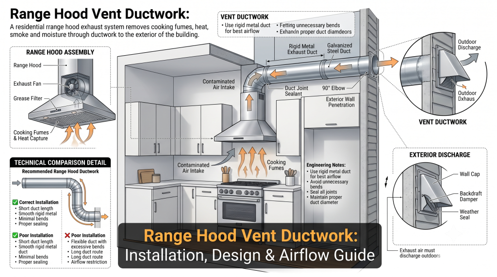
The recommended material is smooth rigid metal, galvanized steel or aluminum, not flexible duct. Flex duct’s corrugated interior traps grease residue, creating a fire hazard over time that rigid smooth-wall duct largely avoids. Many local codes explicitly prohibit flexible duct on range hood exhaust for this reason.
Range hood vent ductwork sizing depends on the CFM rating of the hood. A typical 400 CFM residential hood usually calls for a 6-inch round duct minimum, while higher-capacity hoods (600 CFM and up) often need 8 inches or larger to avoid excessive velocity and backpressure on the fan motor.
The route matters as much as the size. The shortest possible duct run, straight out through a wall or roof with the fewest elbows, gives the best exhaust performance. Every 90-degree elbow adds resistance roughly equivalent to several feet of straight duct, so a run with three or four elbows can quietly cut a hood’s real-world CFM well below its rated capacity, even if the fan itself is working perfectly.
Ductwork Repair and Maintenance
Ductwork repair covers a fairly predictable list of recurring issues:
- Air leakage at joints and seams, usually from failed tape or mastic, or connections that were never properly sealed in the first place.
- Damaged insulation, torn duct wrap or waterlogged fiberglass liner that’s lost most of its R-value.
- Loose connections, disconnected flex duct boots or slipped slip joints, often from foot traffic in an attic or crawlspace.
- Blockages, collapsed flex duct, pest nests, or construction debris left in a run.
- Noise issues, usually traced back to undersized ducts, sharp elbows, or a loose panel vibrating against the duct wall.
Changing Ductwork
Changing ductwork becomes necessary in a handful of common scenarios: a home renovation that moves walls or adds rooms, an HVAC equipment replacement with a different CFM rating than the original system, chronic poor airflow that traces back to undersized branches, or a room addition that needs new supply and return runs entirely. In each case, the existing duct layout has to be reassessed against the new load, not just extended or patched, since the original design was sized for a different set of conditions.
Ductwork Replacement Guide
Signs that point toward full ductwork replacement rather than a repair:
- Old, physically damaged ducts, rusted-through metal or crumbling fiberglass duct board.
- Excessive leakage that a resealing effort can’t bring back under control.
- Mold contamination inside porous ductwork that can’t be cleaned reliably.
- Chronic poor airflow despite equipment servicing and duct sealing attempts.
- Unexplained high energy bills that track back to duct losses rather than equipment inefficiency.
The replacement process itself follows a logical sequence: inspection of the existing system to document its condition, a system evaluation against current loads and equipment (not just a like-for-like swap), removal of the old ductwork, a new duct design sized for the actual load, installation, and finally testing and balancing to confirm the new system delivers what it was designed to deliver.
Mold in Ductwork
Mold in ductwork almost always traces back to moisture, and moisture in a duct system usually comes from one of a few sources: condensation on an undersized or poorly insulated cold supply duct, a clogged or improperly sloped condensate drain pan near the AHU, or high ambient humidity combined with porous duct materials like fiberglass duct board that hold moisture rather than shedding it.
The health concern is straightforward. A duct system is, by design, distributing air to every occupied room in the building. If that air is passing through a contaminated section of duct, mold spores and associated allergens get distributed right along with it, which is a meaningfully different exposure risk than mold isolated to a single closet or wall cavity.
When mold is suspected, the first step is inspection, visual where accessible, sometimes with a borescope for concealed sections, and testing if contamination is confirmed or the extent is unclear. Cleaning can work for smooth metal duct interiors following NADCA (National Air Duct Cleaners Association) standards. Porous materials like fiberglass duct liner or duct board are a different story: once mold has established itself in a porous surface, cleaning rarely removes it completely, and replacement of that section is usually the more reliable fix. Any repair also has to address the moisture source itself, whether that’s better insulation, a repaired drain pan, or improved dehumidification, or the mold simply returns.
Ductwork Design Standards
Duct design in the US isn’t left to guesswork. A handful of standards govern how systems are engineered and verified:
- ASHRAE 62.1 sets ventilation rate requirements, the minimum outdoor air a space needs for acceptable indoor air quality.
- SMACNA (Sheet Metal and Air Conditioning Contractors’ National Association) publishes the HVAC Duct Construction Standards, which define pressure classifications, duct leakage classes (Seal Class A, B, and C, based on how thoroughly joints and seams must be sealed), gauge requirements by duct size and pressure, and hanger spacing.
- IMC (International Mechanical Code) governs duct materials, fire and smoke damper requirements, and installation clearances as adopted by local jurisdictions.
Duct leakage classes matter more than most non-engineers realize. A Class C system (lightly sealed) can leak substantially more than a Class A system (fully sealed at every joint and seam), and the difference shows up directly in delivered airflow and energy consumption. Air balancing requirements, typically referencing NEBB or AABC procedures, exist to verify that the as-built system actually delivers the CFM the design called for, not just that it was installed according to the drawings.
Advantages of Properly Designed Ductwork
A properly sized, sealed, and insulated duct system pays for itself in ways that are easy to overlook until they’re missing:
- Better indoor comfort, even temperatures room to room instead of hot and cold spots.
- Reduced energy consumption, since less conditioned air is lost to leakage or wasted overcoming excess friction.
- Improved indoor air quality, since a sealed system isn’t pulling in unconditioned, potentially contaminated air from attics or crawlspaces through leaky returns.
- Lower operating cost over the life of the system.
- Longer HVAC equipment life, since the blower and compressor aren’t constantly fighting against a poorly designed duct network.
Frequently Asked Questions
What is ductwork in HVAC? Ductwork is the network of enclosed channels, metal, fiberglass, or flexible material, that carries conditioned air between an HVAC unit and the rooms it serves, including both supply ducts (delivering air) and return ducts (bringing air back for reconditioning).
How much does ductwork installation cost? Cost varies widely by region, duct material, and system size, but residential duct replacement commonly runs from a few thousand dollars for a small home to well over ten thousand for a full-house system with extensive rigid metal ductwork. Getting a site-specific quote is the only reliable way to know actual cost.
What type of ductwork is best? There’s no single best answer. Rigid sheet metal and spiral duct offer better durability and lower leakage for long-term performance, while flexible duct offers faster, cheaper installation in tight spaces. Many residential systems use a mix: rigid trunk lines with flexible branch runs.
How long does ductwork last? Rigid metal ductwork, properly installed and sealed, commonly lasts 20 to 25 years or more. Flexible duct has a shorter typical lifespan, often 10 to 15 years, due to insulation settling and physical wear.
Can ductwork be repaired? Yes, in many cases. Leaky joints can be resealed, damaged insulation replaced, and disconnected sections reattached. Severely damaged, crushed, or contaminated ductwork usually needs replacement rather than repair.
How often should ductwork be cleaned? Most sources recommend duct cleaning every 3 to 5 years for typical residential systems, though this can shift earlier if there’s visible contamination, recent renovation dust, pest activity, or known mold.
What size ductwork do I need? Duct size depends on the room or zone’s calculated heating and cooling load, converted to a required CFM, then matched to a duct size using a friction rate chart. It’s not a fixed number, it has to be calculated for the specific space.
Is flexible ductwork better than metal ductwork? Neither is universally better. Flexible duct installs faster and costs less upfront but has higher friction loss if installed poorly and a shorter service life. Metal ductwork costs more and takes longer to install but offers lower leakage, better durability, and generally quieter long-term performance.
How do you insulate ductwork? Ducts running through unconditioned space are typically wrapped in fiberglass duct insulation with a vapor barrier facing (like FSK) installed facing outward, sized to the R-value required by local code, and sealed at every seam to keep the vapor barrier continuous.
How do you calculate ductwork CFM? CFM is calculated from the room’s heating and cooling load using a load calculation method like Manual J, then that airflow requirement is matched to a duct size and velocity using a duct friction rate chart, keeping velocity within acceptable limits to control noise and pressure loss.