


Walk into almost any hotel corridor, hospital ward, or office building with a central chiller plant, and there’s a good chance a fan coil unit is sitting above the ceiling or tucked against the wall a few feet away, quietly doing the actual work of cooling the room. The chiller makes the cold water. The fan coil unit is what turns that cold water into cold air you can feel.
A fan coil unit, or FCU, is a small terminal device built around two things: a fan that moves air, and a coil that either cools or heats it using water piped in from a central plant. That’s the whole idea, and it’s why the name is so literal. Fan coil units are the workhorse of central HVAC systems in the Gulf, Europe, and much of Asia, because they let a single chiller plant condition hundreds of rooms without running full ductwork to every one of them.
This guide covers how a fan coil unit works, what’s inside one, the difference between two-pipe and four-pipe systems, how an FCU compares to a full air handling unit, and what actually happens during installation and maintenance. If you’re an engineer sizing one, a technician troubleshooting a leak, or a homeowner trying to understand the unit humming above your bedroom ceiling, the goal here is to get you to the point where the diagram on the wall actually makes sense.
What Is a Fan Coil Unit (FCU)?
A fan coil unit is a compact air-conditioning terminal that conditions air locally, using chilled or hot water supplied from a central source, rather than generating its own refrigeration like a split AC or window unit does. It has no compressor and no refrigerant circuit of its own. It just moves room air across a water coil.
The name tells you the mechanism:
Fan + Coil = Fan Coil Unit
- Fan — pulls return air in from the room and pushes it back out as supply air.
- Coil — a bank of copper tubes with aluminium fins, where heat moves between the air stream and the water inside.
- Filter — sits ahead of the coil and strips out dust before it can foul the fins.
- Drain pan — catches the water that condenses on a cold coil so it doesn’t drip into the ceiling or onto the floor.
The relationship between the fan and coil is what defines the whole device: air is forced across a wet coil surface, and whatever temperature that water is sitting at gets transferred into the air. Feed it 6-7°C chilled water and the air comes out cold and dehumidified. Feed it 60-70°C hot water and it comes out warm. The fan coil itself doesn’t decide which — that’s set upstream at the chiller or boiler plant, and controlled locally by a valve and thermostat.
This is the core difference between an FCU and a traditional split or window air conditioner. A split system carries refrigerant through the wall to an outdoor condenser and compressor — the cooling is generated at the indoor unit. An FCU HVAC system generates cooling centrally (in a chiller) and just distributes water. That’s a meaningful distinction for a quantity surveyor pricing a project too: FCUs are cheap and simple because most of the expensive equipment — compressors, condensers, refrigerant circuits — lives in one central plant room instead of being duplicated in every room.
Fan Coil Unit Working Principle
The fan coil unit working principle is straightforward once you follow the air and water through the box in sequence.
- Return air enters the FCU through a grille, drawn in by the fan.
- Air passes through the filter, which removes dust and larger particulates before they reach the coil fins.
- The fan pushes air across the coil — usually a centrifugal blower forcing air through the tightly spaced fins.
- Heat exchange happens at the coil. In cooling mode, room air gives up heat to the chilled water running through the copper tubes, and the air also loses moisture as it cools below its dew point (that moisture is what ends up in the drain pan). In heating mode, the reverse happens: the air picks up heat from hot water in the coil.
- Conditioned air is supplied into the room through ductwork or directly through a supply grille.
- Condensate drains away through a trapped drain pipe, laid to a slope so gravity carries the water to a riser or floor drain.
A two-way or three-way control valve, driven by an actuator, sits on the water pipe entering the coil and throttles flow based on signals from a thermostat. The thermostat reads room temperature and adjusts either the valve position, the fan speed, or both, to hold the setpoint. On a modulating three-speed unit, this typically means low-medium-high fan taps controlled manually or by a wall controller, with the valve handling the finer temperature trim.
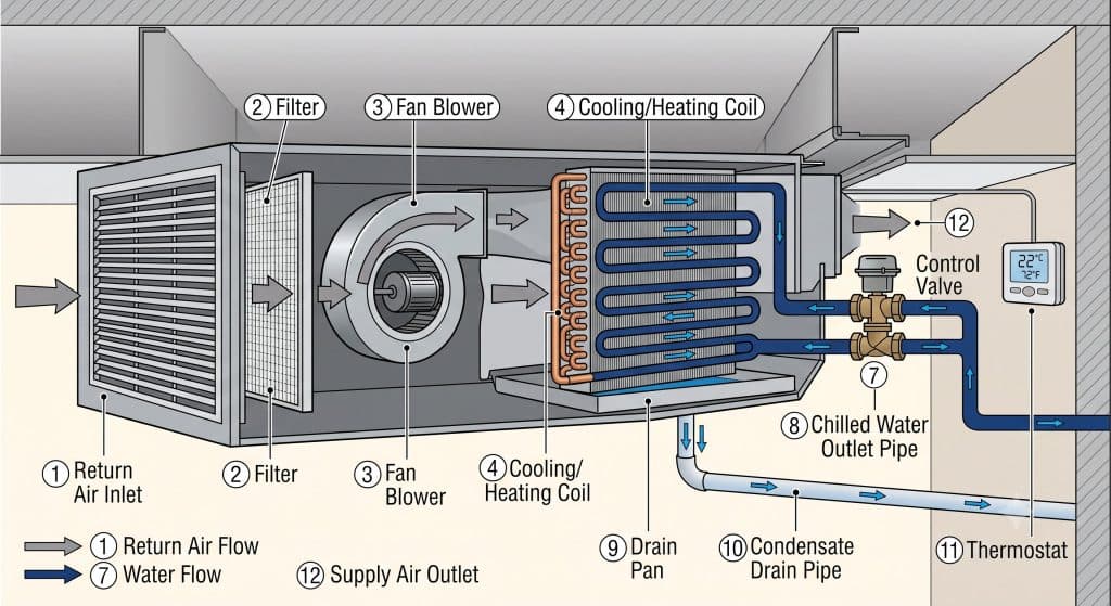
The diagram below shows this sequence laid out physically inside a typical horizontal FCU casing.
Fan Coil Unit Diagram – Reading the Layout
A typical fan coil unit diagram shows two systems overlaid on one casing: the airside and the waterside. Once you can separate the two mentally, reading any FCU schematic — Carrier, Trane, Daikin, whatever the plate says — becomes routine.
Airside path: return air inlet → filter → fan/blower → coil → supply air outlet. This is a straight-through path in most horizontal units, and a bottom-to-top path in vertical floor-mounted units.
Waterside path: chilled (or hot) water inlet pipe → control valve → coil tubes → water outlet pipe, running back to the central plant. The waterside is a closed loop that never mixes with the air; it just exchanges heat through the tube and fin surface.
The components you’ll see labelled on almost every FCU diagram, regardless of manufacturer, are:
- Supply air outlet
- Return air inlet
- Fan blower
- Cooling coil (and heating coil, on four-pipe or electric-heat units)
- Filter
- Chilled water inlet pipe
- Chilled water outlet pipe
- Control valve (2-way or 3-way, with actuator)
- Drain pan
- Condensate drain pipe
- Thermostat or room sensor
If you’re pulling a manufacturer’s submittal drawing for a project, these are exactly the tags to check against the mechanical schedule — pipe sizes, valve type, and drain connection size all get called out against this same layout.

Main Components of a Fan Coil Unit
Every fan coil unit’s components fall into six groups: the fan, the coil, the filter, the drain pan, the control valve, and the thermostat. Each one has its own failure modes and its own maintenance rhythm, so it’s worth knowing what each part is actually doing.
Fan / Blower
Most FCUs use a forward-curved centrifugal fan (a “squirrel cage” blower), because it moves a decent volume of air at low static pressure without much noise — ideal for a device sitting a few feet from someone’s desk or bed. The motor is usually a permanent split capacitor (PSC) or, increasingly, an electronically commutated (EC) motor, wired for 2 or 3 discrete speeds, or continuously variable on EC models. Variable-speed fans let the unit trim airflow to match load without cycling the water valve as hard, which is both quieter and gentler on the coil’s temperature swings.
Cooling and Heating Coil
The coil is a bank of copper tubes mechanically expanded into aluminium fins. Copper carries the water and handles the pressure; the fins multiply the surface area exposed to the airstream, since a bare tube alone wouldn’t transfer enough heat fast enough.
On a chilled water fan coil unit, this coil runs at roughly 6-7°C supply and 12-13°C return, which is cold enough to both cool the air and pull moisture out of it as it passes below the dew point — that’s why FCUs double as dehumidifiers, not just coolers.
A hot water coil runs anywhere from 45°C up to 80°C depending on the boiler plant design. Four-pipe units carry two separate coils in the same casing; two-pipe units use one coil for both duties, switched seasonally.
Air Filter
The filter sits directly ahead of the coil and exists for one reason: keep the fins from clogging. A dirty coil loses airflow and heat transfer fast — a fin bank caked in dust can lose 20-30% of its rated capacity long before anyone notices the room feels warmer. Most FCUs use a washable synthetic media filter (G3/G4 grade under EN 779, or MERV 8 equivalent), rated for cleaning every 4-6 weeks in normal offices and closer to every 2 weeks in dusty construction-adjacent sites or high-occupancy spaces.
Drain Pan
The drain pan sits directly under the coil to catch condensate. It needs to be pitched toward the drain connection — even a millimetre of reverse fall is enough to leave standing water that breeds mould or overflows during a heavy load spell. Stainless steel or coated galvanised pans are standard; plastic pans show up on lower-cost residential units. Insulation on the underside of the pan matters as much as the pan itself, since an uninsulated pan will sweat on its own exterior in humid climates and drip regardless of whether the internal drain is working.
Control Valve
The control valve throttles water flow into the coil based on the thermostat signal. A two-way valve simply opens and closes the flow to that one coil — simple, but it disturbs system-wide water pressure as valves across a building open and close together. A three-way valve diverts water either through the coil or around it via a bypass, keeping flow through the branch roughly constant regardless of load — better for hydronic balance on larger two-pipe systems, at the cost of constant pump energy since water keeps circulating even at zero load. The actuator — electric or, on older systems, pneumatic — is what physically drives the valve stem open or shut.
Thermostat
The thermostat reads room air temperature, sometimes room humidity on higher-end units, and sends a signal to the valve actuator and/or fan speed relay. Basic units use a wall-mounted analog dial; BMS-integrated buildings use a networked digital thermostat (BACnet or Modbus) that reports back to a central building management system, letting facilities staff monitor and schedule hundreds of FCUs from one screen.
Types of Fan Coil Units
Types of fan coil units are usually classified by how they’re installed and oriented in the room, not by how they work internally — the airside and waterside principles above apply to all of them.
Ceiling Concealed Fan Coil Unit
A ceiling concealed fan coil unit sits entirely above the false ceiling, connected to short duct runs feeding supply and return grilles below. Nothing is visible in the room except the grilles themselves. This is the most common type in hotels, offices, and villas across the Gulf, because it keeps the finished ceiling clean and lets the architect control the visual layout without a wall-mounted box interrupting it.
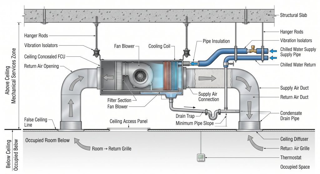
Advantages: hidden installation, clean architectural finish, easy duct distribution to more than one grille from a single unit. Trade-off: access for filter cleaning and coil service means opening a ceiling tile or access panel, so panel placement has to be planned at design stage, not discovered during commissioning.
Ceiling Cassette Fan Coil Unit
A cassette unit also sits above the ceiling but drops a square face flush with the ceiling tile itself, distributing air in four directions from one grille. It’s common in open-plan retail and commercial spaces where a single unit needs to throw air evenly across a squarish floor area without ductwork.
Wall-Mounted Fan Coil Unit
A wall-mounted fan coil unit looks almost identical to a split-system indoor unit — a slim box fixed high on a wall, drawing return air from a bottom or rear grille and discharging supply air from the top. It’s the simplest FCU to install and service since everything is exposed, and it’s common in residential retrofit projects where there’s no false ceiling to conceal ductwork.
Floor-Mounted Fan Coil Unit
A floor-mounted fan coil unit sits at floor level, typically under a window or along a perimeter wall, and throws air upward. This placement matters more than it looks: perimeter zones next to single-glazed or heavily sun-exposed façades carry the largest heat gain (or loss) in a building, and a floor-mounted unit positioned right at that boundary can counter it before it spreads into the room. It’s a standard choice in hotel guest rooms for exactly this reason.
Horizontal and Vertical Fan Coil Units
This is a separate axis of classification from the four types above — it describes the airflow orientation inside the casing rather than the mounting location. Horizontal units (common in ceiling concealed and cassette types) draw air in and discharge it along a horizontal plane. Vertical units (common in floor-mounted types) draw in low and discharge upward. Manufacturers often sell the same coil and fan platform in both orientations, so the internal parts — and their maintenance needs — are largely shared.
Two-Pipe vs Four-Pipe Fan Coil Unit
The pipe count on an FCU tells you whether the system can heat and cool at the same time, or has to pick one and stick with it seasonally.
A two-pipe fan coil unit has a single supply and single return line running to one coil. That coil carries chilled water in summer and hot water in winter, switched over at the central plant — but never both in the same season. It’s cheaper to install (half the piping, half the valves) and works fine in climates with a clear cooling season and heating season. It falls apart in shoulder seasons or mixed-use buildings, where a north-facing room might need heat while a server room on the same floor needs cooling on the same day — a two-pipe system simply can’t serve both.
A four-pipe fan coil unit runs two separate supply/return pairs — one for chilled water, one for hot water — into either one shared coil (with a mixing valve) or two physically separate coils in the same casing. This lets each unit independently call for cooling or heating regardless of what’s happening down the corridor. It costs more upfront in pipe, insulation, and valves, but it’s the standard for hotels and hospitals, where guest comfort and simultaneous heating/cooling demand across different rooms make a two-pipe system impractical.
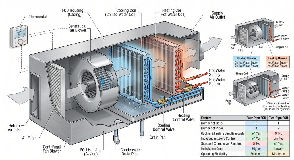
| Feature | Two-Pipe FCU | Four-Pipe FCU |
|---|---|---|
| Pipes | 2 | 4 |
| Cooling | Yes | Yes |
| Heating | Seasonal only | Simultaneous with cooling |
| Installed cost | Lower | Higher |
| Typical application | Residential, small offices | Hotels, hospitals, mixed-load buildings |
Fan Coil Unit vs Air Handling Unit (AHU) vs Split Unit vs DX Unit
Fan Coil Unit vs Air Handling Unit (AHU)
An FCU and an AHU both push air across a water coil — the difference is scale and where the air comes from. An FCU is a small, room-level box. An AHU is a large, centrally located machine that draws air (often a mix of fresh outdoor air and return air) and distributes it through extensive ductwork to many rooms or an entire floor. A Carrier air handler serving an airport terminal or shopping mall, for instance, might move tens of thousands of CFM — several orders of magnitude beyond what any single FCU handles.
| Feature | FCU | AHU |
|---|---|---|
| Size | Small (fits above a ceiling tile or on a wall) | Large (dedicated plant room) |
| Location | Individual rooms/zones | Central mechanical rooms |
| Air volume | Low (typically 200-1,500 CFM) | High (often 5,000+ CFM) |
| Duct connection | Limited, short runs | Extensive, building-wide |
| Fresh air handling | Minimal or none | Dedicated fresh-air intake and mixing |
| Typical application | Offices, hotel rooms, apartments | Airports, malls, hospitals, large floors |

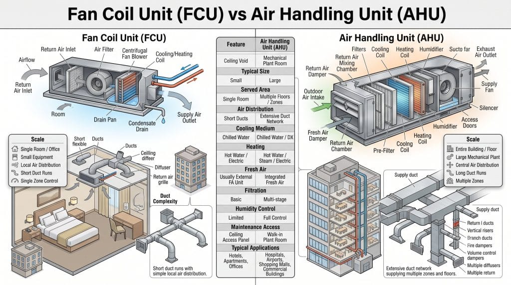
Neither replaces the other — most large buildings run both. AHUs condition and ventilate common areas, corridors, and provide fresh air makeup; FCUs handle the fine-grained, room-by-room temperature control that a central AHU can’t economically do at that resolution.
Where Split Units and DX Units Fit In
“Split unit,” “DX unit,” “FCU,” and “AHU” don’t all sit on the same axis, which is why they get confused. Two things actually vary independently:
- How the cooling is generated — direct expansion (DX), where refrigerant evaporates directly in the coil touching the room air and a compressor sits somewhere in that same refrigerant loop, versus chilled/hot water, where the coil is fed water from a separate central plant and no refrigerant ever reaches the terminal unit.
- What scale the unit serves — a single room versus a whole floor or building through ductwork.
That gives four combinations, not four unrelated products:
| Room-level | Central | |
|---|---|---|
| DX (refrigerant) | Split unit | DX / packaged AHU (rooftop unit) |
| Chilled/hot water | Fan coil unit (FCU) | Chilled water AHU |
The practical dividing line that matters for a spec or a BOQ is standalone versus plant-dependent. A split unit and a DX/packaged AHU carry their own compressor and condenser — refrigerant does the entire job between indoor and outdoor sides, and neither one needs anything else in the building to run. An FCU and a chilled water AHU have no compressor and no refrigerant at all; without chilled or hot water arriving from a central chiller (and usually a boiler), they’re just a fan blowing across a dry coil.
| Split unit | DX / packaged AHU | FCU | Chilled water AHU | |
|---|---|---|---|---|
| Compressor location | Outdoor unit, dedicated to that indoor unit | Rooftop or plant-room packaged unit, dedicated to that AHU | None — no refrigerant in the unit | None — cooling made at a separate central chiller |
| Depends on a central plant? | No — standalone | No — standalone | Yes — dead without chilled/hot water supply | Yes — dead without chilled/hot water supply |
| Fresh air handling | Usually none | Often built in (mixing box, economizer) | Usually none | Almost always built in |
| Zoning flexibility | One outdoor unit tied to one or a few indoor units | Serves whatever ductwork it’s tied to — less granular | Excellent — every room gets its own valve and thermostat | Poor on its own — needs FCUs or VAV boxes downstream for room-level control |
| Typical application | Standalone shops, villas, retrofit rooms | Supermarkets, warehouses, buildings without a chiller plant | Hotels, offices, hospitals on a central plant | Malls, airports, large floors needing fresh air plus bulk conditioning |
If a building already has (or will have) a central chiller plant, FCUs and chilled water AHUs are the natural pairing — one water loop, one plant, no duplicated compressors. Without a chiller plant, DX carries the load instead: split units for individual rooms, packaged or rooftop DX AHUs for larger spaces. On mixed or phased projects — common in Gulf retrofit work — it’s not unusual to find DX split units in one wing and a chilled-water FCU system in another, so it’s worth checking the mechanical schedule carefully during a BOQ review: “AC unit” in a spec can mean any of these four, and the pricing basis is very different between DX and chilled-water equipment.
Fan Coil Unit Installation Process
Installing an FCU HVAC system correctly is less about the unit itself and more about the connections around it. A rushed installation shows up months later as a drain leak or a noisy fan, not on day one.
- Location selection. Confirm ceiling void depth (or wall clearance for wall-mounted units) is sufficient for the unit, its service clearance, and pipe/duct connections before the unit arrives on site.
- Support installation. Hangers or brackets are fixed to the structural slab, sized for the unit’s operating weight plus water fill — not just the dry shipping weight.
- FCU mounting. The unit is lifted into place and levelled; a unit installed out of level will pitch the internal drain pan incorrectly no matter how well the drain pipe itself is sloped.
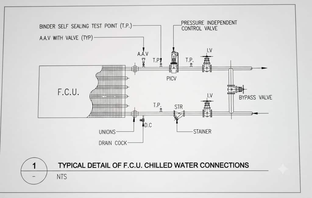
- Chilled/hot water pipe connection. Supply and return pipes are connected to the coil, typically with unions for future servicing, and pressure-tested before insulation goes on.
- Pipe insulation. Chilled water pipe insulation has to be continuous and vapour-sealed — any gap becomes a condensation point in a humid climate, which is one of the most common defects found on site handover in the Gulf.
- Drain pipe installation. The condensate line is run with a continuous fall (commonly 1-2% minimum) to a riser or gravity drain, with a trap to stop odour and insects coming back up the line.
- Electrical connection. Power and control wiring is run to the fan motor and valve actuator, following the unit’s wiring diagram.
- Thermostat installation. Mounted at a representative height on an internal wall, away from direct sun or supply air discharge that would give a false reading.
- Testing and commissioning. Airflow is measured and balanced against design CFM, water flow is balanced against design GPM/L·s, and the control loop is checked for stable temperature response before handover.
Access for maintenance deserves its own line item at design stage — an FCU installed with no access panel above it, or buried behind finished millwork, turns a five-minute filter change into a half-day job later.

Fan Coil Unit Maintenance
Monthly maintenance:
- Clean or replace air filters.
- Check supply airflow by hand or with a simple anemometer — a noticeable drop usually means a dirty filter or coil.
- Inspect the drain pan and line for standing water or slow drainage.
Periodic (quarterly to annual) maintenance:
- Clean the coil fins with a soft brush or low-pressure wash — a fin comb can straighten bent fins that restrict airflow.
- Inspect the motor for bearing noise or excessive vibration.
- Check the control valve for correct open/close travel and look for signs of the actuator sticking.
- Inspect electrical connections and terminals for corrosion, especially in coastal or high-humidity sites.
Common problems and their usual cause:
| Problem | Usual Cause |
|---|---|
| Water leakage | Blocked or poorly pitched drain, cracked pan, condensation on uninsulated pipe |
| Poor cooling | Dirty filter/coil, low water flow, stuck valve, low refrigerant… n/a for FCU — check chilled water supply temperature at plant |
| Noisy fan | Worn bearings, loose fan wheel, debris in blower housing |
| Low airflow | Clogged filter, blocked coil fins, fan speed set too low |
| Blocked drain | Algae growth, debris in the trap, insufficient fall in the drain pipe |
Fan Coil Unit Models and Manufacturers
Several manufacturers dominate the FCU market, each with model ranges spanning ceiling concealed, cassette, wall-mounted, and floor-mounted configurations:
- Addison fan coil unit models — widely specified across Gulf hotel and commercial projects, known for compact chassis options in ceiling concealed and floor-mounted formats.
- Carrier fan coil units — one of the most recognised names globally, with both two-pipe and four-pipe ranges and tight integration with Carrier chiller plants.
- Trane FCU — common in commercial and institutional projects, with strong BMS/BACnet integration options.
- Daikin FCU — popular in residential and light commercial applications, often paired with Daikin’s own chiller and VRF equipment lines.
- Johnson Controls FCU — frequently specified in projects already standardised on Johnson Controls building automation.
Model selection factors typically come down to:
- Cooling/heating capacity required for the space.
- Rated airflow (CFM or L/s) at the design external static pressure.
- Available static pressure if ducted to more than one grille.
- Installation type — ceiling concealed, cassette, wall, or floor.
- Two-pipe vs four-pipe compatibility with the building’s central plant.
Fan Coil Unit Capacity Selection
Sizing an FCU starts with the room’s actual cooling (or heating) load, not a rule-of-thumb square-footage guess. Key inputs:
- Room cooling load — calculated from solar gain, internal heat gain (occupants, lighting, equipment), and envelope losses/gains, usually expressed in BTU/hr or kW.
- Room size and occupancy — larger occupied spaces need proportionally more airflow, expressed in CFM or L/s, to maintain air movement and comfort, not just raw cooling capacity.
- Heat gains from glazing and equipment — a west-facing room with floor-to-ceiling glass carries a very different load than an interior room of the same floor area.
- Chilled water supply temperature — the coil’s rated capacity assumes a specific entering water temperature (commonly 6-7°C); running warmer water through it (a common issue on an overloaded chiller plant) cuts real delivered capacity below the nameplate number.
Undersizing leaves a room that never quite reaches setpoint on the hottest days. Oversizing wastes capital cost and can cause short-cycling, which hurts dehumidification since the coil never runs long enough to pull moisture out properly.
Advantages and Disadvantages of Fan Coil Units
Advantages:
- Energy efficient compared to running full ductwork and a large AHU to condition small, separate zones.
- Individual zone control — each room’s thermostat is independent of every other room.
- Compact size, easy to conceal above a ceiling or against a wall.
- Comparatively easy maintenance — most service items (filter, coil access, drain) are reachable without specialist tools.
- Flexible installation across ceiling concealed, cassette, wall, and floor formats.
Disadvantages:
- Requires regular filter cleaning or performance drops quickly.
- Limited fresh air capability on its own — most FCUs recirculate room air and rely on a separate fresh air system or AHU for ventilation.
- Can generate noticeable noise if the fan or bearings aren’t maintained.
- Condensation issues if installed without correct drain slope or pipe insulation.
Applications of Fan Coil Units
Fan coil units show up anywhere a building needs many independently controlled zones fed from one central chilled/hot water plant:
- Hotels — guest rooms, corridors, function rooms
- Apartments and residential towers
- Offices — individual rooms and open-plan zones
- Hospitals — wards and patient rooms, often on four-pipe systems for simultaneous heating/cooling needs
- Shopping malls — retail units and back-of-house spaces
- Schools — classrooms and administrative offices
- Villas and residential buildings across the Gulf, where ducted split systems and central chilled water FCU systems both compete for the same market
Frequently Asked Questions
What is a fan coil unit? A fan coil unit is a small HVAC terminal device that uses a fan to move room air across a water coil, cooling or heating it using chilled or hot water supplied from a central plant, rather than generating cooling on its own.
How does a fan coil unit work? Return air is drawn in through a filter, pushed by a fan across a coil carrying chilled or hot water, and supplied back into the room. A thermostat and control valve regulate water flow to hold the setpoint, and condensate from the cooling process drains away through a sloped drain line.
What is the difference between FCU and AHU? An FCU is a small unit serving one room or zone with low airflow and no fresh-air handling; an AHU is a large central machine, often paired with a Carrier air handler-class unit, serving many zones through extensive ductwork and usually handling fresh air intake as well.
Is FCU better than split AC? Neither is universally “better” — an FCU relies on a central chilled water plant and suits buildings with many zones, while a split AC has its own self-contained refrigeration circuit and suits standalone spaces without a central plant. FCUs tend to be more cost-effective at building scale; split systems are simpler for single, isolated rooms.
How often should FCU filters be cleaned? Typically every 4-6 weeks in normal office or residential use, and as often as every 2 weeks in dusty environments or high-occupancy spaces.
What is a four-pipe fan coil unit? A four-pipe FCU runs separate chilled water and hot water supply/return pipes to the same unit, letting it heat and cool independently of every other unit on the system — standard in hotels and hospitals where simultaneous heating and cooling demand across different rooms is common.
What is the difference between fan coil and air handler? A fan coil is a small, room-level device; an air handler (AHU) is a large, centrally located unit that conditions and distributes air to many rooms through ductwork. Both use the same basic fan-and-coil principle, just at very different scales.
Conclusion
A fan coil unit is a simple idea executed well: a fan moving air, a coil exchanging heat with water from a central plant, wrapped in a box small enough to hide above a ceiling tile. Understanding the working principle — return air, filter, fan, coil, supply air, drain — makes every FCU diagram from every manufacturer readable at a glance. Getting the type right (ceiling concealed, cassette, wall, or floor), the pipe configuration right (two-pipe or four-pipe), and the capacity right against the actual room load is what separates a fan coil unit installation that runs quietly for fifteen years from one that’s back on the maintenance call list every summer.
Whether you’re specifying an HVAC fan coil system for a new hotel tower or troubleshooting a single noisy unit above a bedroom ceiling, the same fundamentals apply — get the fan and coil sized to the load, the water and drain pipes installed correctly, and the maintenance schedule kept up, and the rest takes care of itself.