


Introduction
Walk onto almost any active construction site and you’ll find a centrifugal pump running somewhere – dewatering a foundation pit, feeding a curing water tank, or circulating chilled water through an HVAC loop. These machines show up everywhere because they solve a basic problem well: moving liquid from one point to another, reliably, for long stretches of time, without much fuss.
A centrifugal pump converts the rotational energy of a motor into kinetic and pressure energy in a fluid. That’s the whole job in one sentence. But the way it does this – spinning an impeller inside a casing shaped to convert speed into pressure – is worth understanding in detail if you work with water supply systems, plumbing networks, fire protection, sewage treatment, or industrial process piping.
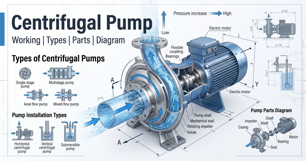
This article covers what a centrifugal pump is, how it works step by step, the parts that make it up, the different types you’ll run into on a project, and how engineers actually select one for a given application. Expect a labelled diagram, formulas, comparison tables, and a troubleshooting section worth bookmarking for when a pump on site starts acting up.
What is a Centrifugal Pump?

In plain terms: a centrifugal pump is a machine that uses a spinning impeller to push liquid outward, and a shaped casing around that impeller to turn that outward push into usable pressure. Water goes in near the center of the impeller, gets flung to the outer edge by the spin, and exits under pressure through a discharge pipe. That’s the beginner version, and it’s enough to picture what’s happening inside the machine.
For engineers, the more precise definition is that a centrifugal pump is a type of rotodynamic pump that converts mechanical energy supplied by a prime mover, usually an electric motor, into hydraulic energy through the rotation of an impeller. The energy transfer happens continuously as long as the impeller keeps turning, which is why centrifugal pumps deliver a smooth, steady flow rather than pulses.
This distinguishes them from positive displacement pumps, which trap a fixed volume of fluid in a chamber and force it out mechanically, one stroke or one rotation at a time. A piston pump or a gear pump moves the same volume of fluid on every cycle regardless of the pressure it’s working against. A centrifugal pump doesn’t work that way. Its flow rate depends heavily on the resistance in the system: raise the discharge pressure and the flow drops; lower it and the flow climbs. That relationship is described by the pump’s performance curve, something every manufacturer publishes and every specification should reference before a pump gets ordered.
Centrifugal Pump Working Principle
How does a centrifugal pump work?
The working sequence is straightforward once you follow it step by step:
- The motor drives the pump shaft, usually through a direct coupling.
- The shaft rotates the impeller inside the casing, typically between 1450 and 2900 rpm for standard electric-driven pumps.
- Water enters through the suction pipe and arrives at the eye of the impeller, the low-pressure zone at its center.
- The spinning impeller vanes catch this water and fling it outward under centrifugal force.
- As the water moves from the impeller eye to its outer rim, its velocity increases sharply.
- The casing, shaped as a volute (a spiral that widens as it approaches the discharge), slows the water down in a controlled way. This is where velocity energy converts into pressure energy.
- Pressurized water exits through the discharge outlet into the delivery pipe.
Two forms of energy matter here. Velocity head is the energy the water carries because it’s moving fast, proportional to velocity squared. Pressure head is the energy stored as static pressure. The volute casing exists specifically to convert one into the other efficiently, so a pump spinning at high rpm ends up delivering steady pressure rather than a fast, low-pressure jet.
On the suction side, the pump relies on atmospheric pressure, or positive suction head from an elevated tank, to push water into the eye of the impeller. This is why priming matters: if there’s air instead of water at the impeller eye when the pump starts, the impeller has nothing to grip and no pressure builds. On the discharge side, the pump adds head to overcome pipe friction, elevation, and whatever pressure the downstream system requires.
Centrifugal Pump Diagram
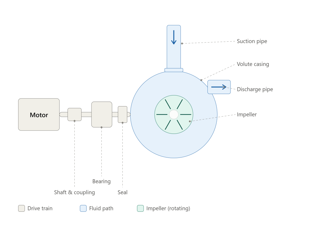
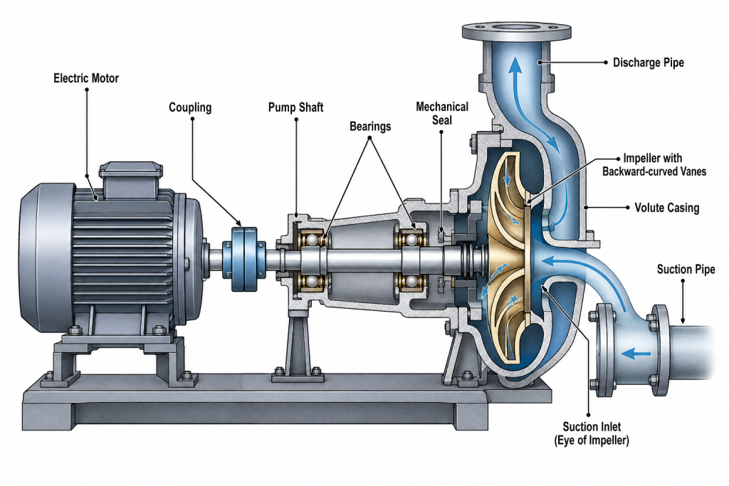
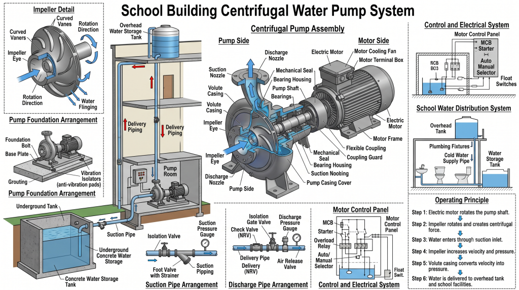
A labelled diagram makes the working principle click faster than any amount of text. The key components to look for on a centrifugal pump cross-section are:
- Motor – supplies rotational power
- Shaft – transmits that power from motor to impeller
- Coupling – connects motor shaft to pump shaft
- Bearing – supports the shaft and keeps it aligned
- Mechanical seal – stops water from leaking along the shaft
- Impeller – the rotating component that does the actual pumping
- Volute casing (pump casing) – houses the impeller and converts velocity into pressure
- Suction pipe and suction inlet – bring water into the impeller eye
- Discharge pipe – carries pressurized water out of the pump
In the diagram, the motor and drivetrain sit on one side, the volute casing and impeller on the other, with the suction pipe entering from above the casing and the discharge pipe exiting to the side. The suction inlet is simply the point where the suction pipe meets the casing and delivers water directly to the impeller eye.

Main Parts of a Centrifugal Pump
Impeller
The impeller is the only moving part in contact with the fluid. It has curved vanes that accelerate water outward as it spins. Impellers come in three basic types:
- Open impeller – vanes attached to a hub with no shrouds, easiest to clean, used for fluids carrying suspended solids
- Semi-open impeller – vanes attached to one shroud, a middle-ground design between open and closed
- Closed impeller – vanes enclosed between two shrouds, highest efficiency, best suited to clean fluids
Pump Casing
The casing surrounds the impeller and directs flow toward the discharge. Two designs dominate:
- Volute casing – a spiral-shaped casing that widens gradually as it approaches the discharge, converting velocity into pressure through the changing cross-sectional area
- Diffuser casing – uses stationary guide vanes around the impeller to straighten and slow the flow before it reaches the casing, common in multistage pumps where efficiency at each stage matters
Shaft
The shaft transfers rotational energy from the motor, through the coupling, to the impeller. It needs to be stiff enough to resist bending under the radial and axial loads the impeller generates, and precisely aligned to avoid vibration.
Mechanical Seal
Positioned where the shaft passes through the casing, the mechanical seal keeps pressurized water from leaking out along the rotating shaft. It consists of a stationary face and a rotating face, held together under spring pressure, with a thin film of fluid between them for lubrication. Older pumps used packed gland seals instead, which allow a small, deliberate drip for cooling; mechanical seals are now the standard for most applications because they leak far less.
Bearings
Bearings support the shaft radially and axially, keeping it centered inside the casing and absorbing the thrust the impeller generates. Bearing failure is one of the more common reasons pumps get pulled for maintenance, usually traced back to lubrication problems or misalignment.
Suction Pipe
Draws water from the source, whether that’s a sump, a tank, a well, or a supply main, into the pump. Suction pipe sizing and layout matter more than people expect. An undersized or poorly routed suction pipe is a leading cause of cavitation.
Discharge Pipe
Carries pressurized water from the pump to its destination. Discharge piping typically includes a check valve close to the pump to prevent backflow when the pump stops, and an isolation valve for maintenance.
Motor
Almost always an electric induction motor in building and industrial applications, sized to match the power the pump needs at its design flow and head, with enough margin to cover the full range of the pump curve rather than just the single design point.
| Component | Function |
|---|---|
| Impeller | Creates centrifugal force, accelerates fluid outward |
| Casing | Converts velocity into pressure |
| Shaft | Transfers rotational energy from motor to impeller |
| Mechanical seal | Prevents leakage along the shaft |
| Bearings | Support and align the rotating shaft |
| Suction pipe | Delivers fluid into the impeller eye |
| Discharge pipe | Carries pressurized fluid to the delivery point |
Types of Centrifugal Pumps
Based on Number of Impellers
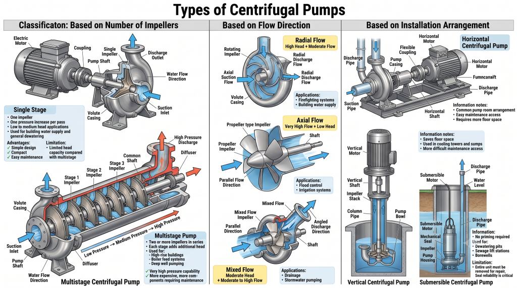
Single stage centrifugal pump – one impeller, one pressure boost per pass. Suits low to medium head applications such as building water supply and general dewatering. Advantage: simple, compact, easy to maintain. Limitation: head is capped by what a single impeller can generate, so it runs out of pressure on tall or long-distance systems.
Multistage centrifugal pump – two or more impellers arranged in series on the same shaft, each stage adding head to what the previous one produced. Used where high pressure is required: boiler feed applications, high-rise water supply, deep well pumping. Advantage: reaches pressures a single stage can’t. Limitation: more complex, more expensive, and more parts that can wear or misalign.
Based on Flow Direction
Radial flow pump – the most common type. Water enters axially and leaves radially at 90 degrees to the shaft. Suited to high head, moderate flow applications such as building water supply and firefighting. Limitation: not efficient at very high flow rates.
Axial flow pump – water moves parallel to the shaft, pushed forward like a propeller rather than flung outward. Delivers very high flow at low head, used in flood control and irrigation. Limitation: cannot generate significant pressure, so it’s the wrong choice wherever head matters more than volume.
Mixed flow pump – a middle ground, water leaves at an angle between radial and axial, balancing moderate head with moderate to high flow. Used in drainage and stormwater applications. Limitation: a compromise design, so it won’t outperform a radial pump on head or an axial pump on flow.
Based on Installation
Horizontal centrifugal pump – shaft mounted horizontally, the most familiar layout in pump rooms, easy to access for maintenance. Limitation: needs more floor space and a flooded or primed suction line.
Vertical centrifugal pump – shaft mounted vertically, saves floor space, common in sumps and cooling tower applications. Limitation: harder to access for shaft and bearing maintenance without lifting equipment.
Submersible centrifugal pump – motor and pump sealed as one unit and submerged directly in the fluid, no priming required, the standard choice for dewatering pits, sewage lift stations, and borewells. Limitation: the motor sits in the wet environment, so seal integrity is critical, and repairs mean pulling the whole unit out.
Each type trades off cost, footprint, maintenance access, and suction conditions differently, which is exactly why pump room drawings specify type, not just performance figures.

Centrifugal Water Pump
A centrifugal water pump is simply a centrifugal pump configured for handling water rather than oil, chemicals, or slurry, though the underlying machine is the same. You’ll find this exact term used across:
- Building water supply, boosting municipal or tank-fed pressure to upper floors
- Irrigation systems, drawing from a source and distributing across a field
- Firefighting systems, where NFPA and local fire codes set strict performance and reliability requirements
- HVAC systems, circulating chilled and hot water between plant and terminal units
- Drainage systems, moving stormwater or wastewater away from a site
- Industrial plants, transferring process fluids between stages
Selecting the right centrifugal water pump for any of these comes down to a handful of factors: the flow rate the application demands, in L/s or m³/hr; the total head the pump needs to overcome; the power available and required; the efficiency at the actual operating point rather than just the best efficiency point on the curve; and the quality of the water, since sediment or corrosive content changes material selection for the impeller, casing, and seal.
Applications of Centrifugal Pumps
- Construction site dewatering, clearing foundation pits and excavations
- Water transfer between tanks, reservoirs, and treatment stages
- Plumbing systems, boosting pressure in multi-story buildings
- Cooling tower water circulation
- HVAC chilled water and hot water circulation
- Fire protection systems, including fire hydrant and sprinkler networks
- Sewage treatment plants, moving raw and treated effluent through the process
- Agricultural irrigation
- Industrial process fluid transfer
Advantages of Centrifugal Pumps
- Simple construction with few moving parts, which keeps manufacturing and repair costs down
- Continuous, smooth flow rather than pulsating delivery
- Low maintenance relative to positive displacement pumps
- Handles large flow rates efficiently
- Compact footprint for the flow and head it delivers
- Easy to operate and automate with standard motor controls
Disadvantages of Centrifugal Pumps
- Cannot handle very high viscosity fluids efficiently; efficiency drops sharply as viscosity rises
- Requires priming before starting, since it can’t move air the way it moves water
- Efficiency falls off at flow rates away from the best efficiency point
- Sensitive to cavitation if suction conditions aren’t right
- Not the right choice for very high pressure, low flow applications, where positive displacement pumps do better
Centrifugal Pump vs Positive Displacement Pump
| Feature | Centrifugal Pump | Positive Displacement Pump |
|---|---|---|
| Working principle | Converts rotational energy into velocity, then pressure | Traps and pushes a fixed volume of fluid each cycle |
| Flow | Continuous, varies with system pressure | Constant regardless of pressure, until the driver stalls |
| Pressure | Builds gradually, drops if flow increases | Can generate very high pressure at low flow |
| Fluid type | Best for low to medium viscosity fluids | Handles high viscosity and shear-sensitive fluids well |
| Maintenance | Generally lower, fewer wear points | Higher, more seals and moving parts |
| Applications | Water supply, HVAC, dewatering, firefighting | Metering, chemical dosing, hydraulics, oil transfer |
Centrifugal Pump Selection Guide
Selecting a centrifugal pump for a project comes down to matching the pump curve to the system curve at the right operating point. Engineers typically work through:
- Required flow rate, in L/s or m³/hr, based on peak demand for the system being served
- Total Dynamic Head (TDH), the sum of static head, friction losses in piping and fittings, and any residual pressure required at the delivery point
- Suction conditions, checking Net Positive Suction Head Available (NPSHa) against the pump’s NPSHr to avoid cavitation
- Pump efficiency at the actual operating point, not just at the best efficiency point on the published curve
- Motor power, sized with margin above the hydraulic power demand to cover startup and any curve variation
- Operating conditions, including fluid temperature, ambient conditions, and duty cycle, continuous versus intermittent
Hydraulic Power Formula
P = ρ × g × Q × H
Where:
- P = hydraulic power (watts)
- ρ = density of the fluid (kg/m³, approximately 1000 for water)
- g = gravitational acceleration (9.81 m/s²)
- Q = flow rate (m³/s)
- H = pump head (meters)
As an example, a pump delivering 0.05 m³/s (50 L/s) against a head of 30 meters needs a hydraulic power of roughly 1000 × 9.81 × 0.05 × 30 = 14,715 watts, about 14.7 kW. Divide by the pump’s efficiency, commonly 65-75% for medium-sized centrifugal pumps, to get the shaft power the motor actually has to supply. In this example that works out to roughly 19.6 to 22.6 kW, which is the figure that should drive motor selection, not the bare hydraulic power.
Common Centrifugal Pump Problems
| Problem | Common Cause | Solution |
|---|---|---|
| Cavitation | Insufficient NPSH, suction pipe too long or too small, blocked strainer | Improve suction layout, lower pump elevation relative to source, clear blockages |
| Low discharge pressure | Worn impeller, wrong rotation direction, air in system | Inspect and replace impeller, check motor wiring phase, bleed air |
| Leakage | Worn or damaged mechanical seal | Replace seal, check shaft alignment |
| Excessive vibration | Misalignment, worn bearings, impeller imbalance | Realign shaft, replace bearings, balance or replace impeller |
| Bearing failure | Poor lubrication, misalignment, contamination | Follow lubrication schedule, correct alignment, seal bearing housing properly |
| Air locking | Air trapped at the pump casing, especially on start-up | Install an air release valve, check the priming procedure |
| Overheating | Running against a closed valve, insufficient flow, bearing friction | Never run against a closed discharge valve for long, respect the minimum flow requirement |
Maintenance of Centrifugal Pump
Routine maintenance keeps a centrifugal pump running for its full service life rather than failing early:
- Regular visual inspection for leaks, unusual noise, and corrosion
- Vibration monitoring to catch bearing wear or misalignment before it becomes a failure
- Lubrication of bearings on the manufacturer’s recommended schedule, not by guesswork
- Mechanical seal inspection, watching for weeping or dripping at the seal face
- Shaft and coupling alignment checks, particularly after any reinstallation
- Cleaning suction strainers and filters to prevent blockage and cavitation
- Monitoring flow, pressure, and power draw against the original commissioning data to catch gradual performance drop before it becomes a breakdown
Frequently Asked Questions
What is a centrifugal pump? A centrifugal pump is a rotodynamic pump that uses a spinning impeller to convert mechanical energy from a motor into velocity and pressure energy in a fluid, moving it from a suction source to a discharge point.
How does a centrifugal pump work? The motor spins the impeller inside a casing. Fluid enters at the impeller eye, gets accelerated outward by the vanes, and the volute or diffuser casing converts that velocity into pressure before the fluid exits through the discharge pipe.
What are the main parts of a centrifugal pump? The core parts are the impeller, casing, shaft, mechanical seal, bearings, suction pipe, and discharge pipe, all driven by a motor through a coupling.
What are the different types of centrifugal pumps? Centrifugal pumps are classified by number of impellers (single stage, multistage), flow direction (radial, axial, mixed), and installation (horizontal, vertical, submersible).
What is the difference between centrifugal and positive displacement pumps? A centrifugal pump uses a spinning impeller and delivers flow that varies with system pressure. A positive displacement pump traps and pushes a fixed volume of fluid each cycle, delivering nearly constant flow regardless of pressure.
What is a centrifugal water pump used for? It’s used for building water supply, irrigation, firefighting systems, HVAC circulation, drainage, and industrial water transfer.
Why does a centrifugal pump need priming? Because it relies on centrifugal force acting on liquid to build pressure. Air is too light for the impeller to generate meaningful pressure, so if the casing and suction line are filled with air instead of liquid at startup, the pump won’t move fluid until it’s primed.